Automobile rear anti-collision beam optimization method based on CAE (Computer Aided Engineering) crash simulation technology

An optimization method and technology of rear anti-collision beam, applied in geometric CAD, design optimization/simulation, special data processing applications, etc., to achieve the effect of low development cost, meeting performance requirements, and light weight

Pending Publication Date: 2018-05-04
BRILLIANCE AUTO
View PDF0 Cites 1 Cited by
  • Summary
  • Abstract
  • Description
  • Claims
  • Application Information

AI Technical Summary

Problems solved by technology

[0005] Usually in the event of a rear low-speed collision or a rear collision, two key issues are raised in the project: 1. Control development costs, starting from the rear bumper beam; 2. While saving costs, it is also necessary to meet the conditions of rear collision and Performance requirements for rear low-speed collision conditions
The above poses a great challenge to engineers

Method used


Image

  • Automobile rear anti-collision beam optimization method based on CAE (Computer Aided Engineering) crash simulation technology
  • Automobile rear anti-collision beam optimization method based on CAE (Computer Aided Engineering) crash simulation technology

Examples


Example Embodiment

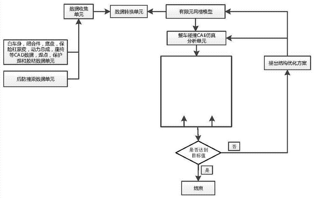
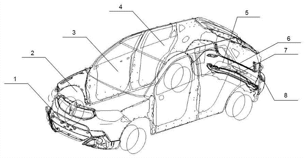
[0016] The invention provides a method for optimizing automobile rear anti-collision beams based on CAE collision simulation technology, which includes CAD data such as body-in-white, closures, chassis, bumper skins, powertrains, seats, solder joints, protective welding and glue For sticky data units, the optimization method includes the following steps:

[0017] (1) The above-mentioned units transfer data to the data collection unit, and the data collection unit transfers the data to the data conversion unit;

[0018] (2) The data conversion unit is the finite element pre-processing ANSA software that converts the data in the data collection unit into the connection format recognized by the software, in which the 3D point of the solder joint data is converted to spotweld, and the protective welding CAD line is converted to spotline. The CAD plane is converted to an adhesive face, the diameter of the solder joint, the interval of the protective welding and the width of the expansion g


PUM


Abstract

The invention provides an optimization method for replacing plastic with metal for an automobile rear anti-collision beam for a CAE (Computer Aided Engineering) crash simulation technology. On the basis of the CAE crash simulation technology and the rear anti-collision beam of traditional metal, the rear anti-collision beam of the traditional metal is changed into the rear anti-collision beam of plastic, a verification result shows that a rear collision working condition and a rear low-speed collusion working condition CAE analysis result meet a target value requirement, and a rear automobileexperiment verifies that the rear collision of the rear anti-collision beam of plastic and rear low-speed collision meet requirements. The rear anti-collision beam of plastic has the advantages of light quality, corrosion resistance, fatigue resistance, good toughness and low cost.

Description


Claims


Application Information

Patent Timeline
Owner BRILLIANCE AUTO
Why Eureka
Try Eureka