All steel scrap smelting iron-casting system

An all-scrap and cast iron technology, which is applied in the field of smelting cast iron from scrap steel, can solve the problems of affecting the processing progress, slow cooling speed of molten iron, and low smelting efficiency, and achieve the effects of improving work progress, reducing the loss of molten iron, and accelerating cooling speed

Pending Publication Date: 2018-06-05
江西亿丰精密铸造有限公司
View PDF4 Cites 1 Cited by
  • Summary
  • Abstract
  • Description
  • Claims
  • Application Information

AI Technical Summary

Problems solved by technology

[0003] The purpose of the present invention is to provide an all-scrap steel smelting cast iron system to solve the problem that some large pieces of steel and small pieces of steel are bonded together during the smelting process of the current

Method used


Image

  • All steel scrap smelting iron-casting system
  • All steel scrap smelting iron-casting system
  • All steel scrap smelting iron-casting system

Examples


Embodiment Construction

[0019] The following will clearly and completely describe the technical solutions in the embodiments of the present invention with reference to the accompanying drawings in the embodiments of the present invention. Obviously, the described embodiments are only some, not all, embodiments of the present invention. Based on the embodiments of the present invention, all other embodiments obtained by persons of ordinary skill in the art without making creative efforts belong to the protection scope of the present invention.

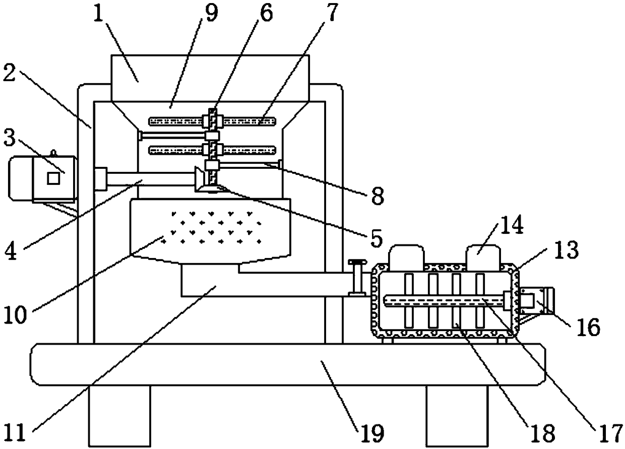
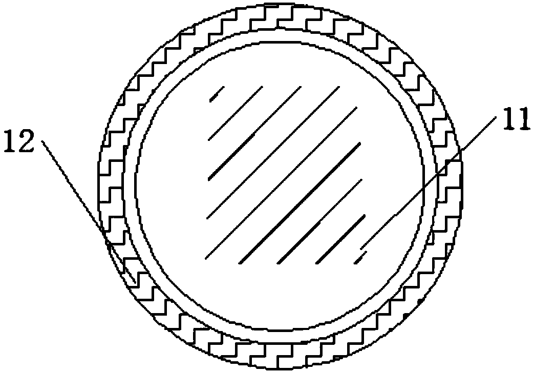
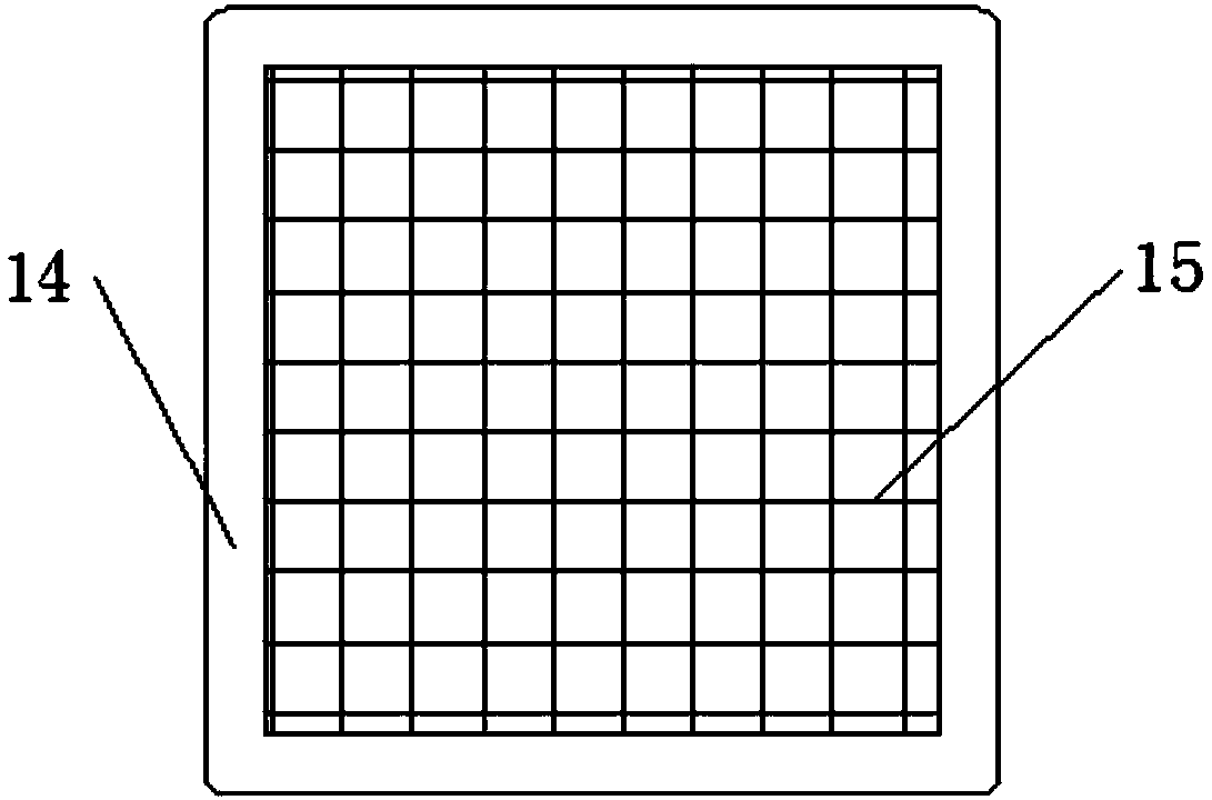
[0020] see Figure 1-3 , the present invention provides a technical solution: a whole scrap steel smelting cast iron system, including a feed port 1, a machine body 2, a first motor 3, a rotating shaft 4, a bevel gear 5, a connecting rod 6, a breaking blade 7, a support rod 8. Dispersion chamber 9, melting chamber 10, connecting pipe 11, sealing ring 12, molten iron tank 13, cooling vent 14, filter screen 15, second motor 16, stirring shaft 17, stirring blade 18


PUM


Abstract

The invention discloses all steel scrap smelting iron-casting system which comprises a feed inlet, a supporting rod, a molten iron box and a base, wherein a body is fixed below the feed inlet, and a first motor is arranged on the left side of the body; a rotary shaft is mounted at the right end of the first motor, and the right side of the rotary shaft is connected to a cone-shaped gear; the feedinlet is formed in the upper side of the supporting rod, and the supporting rod is connected to the inner wall of a scattering chamber; a smelting chamber is arranged below the scattering chamber, anda connecting pipe is mounted in the bottom of the smelting chamber; and the left end of a second motor is connected to a stirring shaft, and stirring blades are fixed around the stirring shaft. The all steel scrap smelting iron-casting system can accelerate molten iron cooling, the scattering chamber is arranged below the feed inlet, the connecting rod is arranged on the inner side of the scattering chamber, and the scattering blades are mounted around the connecting rod, so that steel and iron blocks adhered together are scattered, and therefore, the steel and iron smelting efficiency is accelerated.

Description


Claims


Application Information

Patent Timeline
Owner 江西亿丰精密铸造有限公司
Why Eureka
Try Eureka