Humidity control device, temperature control system of humidity control device and photolithography cabinet

A temperature control system and humidity control technology, which is applied to the exposure device of photoengraving process, air conditioning system, opto-mechanical equipment, etc. rate, to ensure the effect of normal work

Inactive Publication Date: 2018-07-03
HUAIAN IMAGING DEVICE MFGR CORP
View PDF5 Cites 1 Cited by
  • Summary
  • Abstract
  • Description
  • Claims
  • Application Information

AI Technical Summary

Benefits of technology

This technology helps maintain an optimal level for each piece of manufacturing equipment used during photolithographic processes while ensuring they are working properly without causing problems such as electrostatic discharge (ESD) caused by high levels of moisture being introduced into these devices.

Problems solved by technology

This technical problem addressed in this patents relates to controlling the amount of moisturized indoor air supplied during photolithographic processing without causing instability issues like electrostatic discharge caused by high levels of condensed mist generated when removing dust particles off surfaces being processed.

Method used


Image

  • Humidity control device, temperature control system of humidity control device and photolithography cabinet
  • Humidity control device, temperature control system of humidity control device and photolithography cabinet
  • Humidity control device, temperature control system of humidity control device and photolithography cabinet

Examples


Embodiment Construction

[0041] The humidity control device, its temperature control system, and the photolithography machine proposed by the present invention will be further described in detail below with reference to the accompanying drawings and specific embodiments. The advantages and features of the present invention will become clearer from the following description. It should be noted that all the drawings are in a very simplified form and use imprecise scales, and are only used to facilitate and clearly assist the purpose of illustrating the embodiments of the present invention.

[0042] As used in this specification, the singular forms "a", "an" and "the" include plural referents unless the content clearly dictates otherwise. As used in this specification, the term "or" is generally employed in its sense including "and / or" unless the content clearly dictates otherwise.

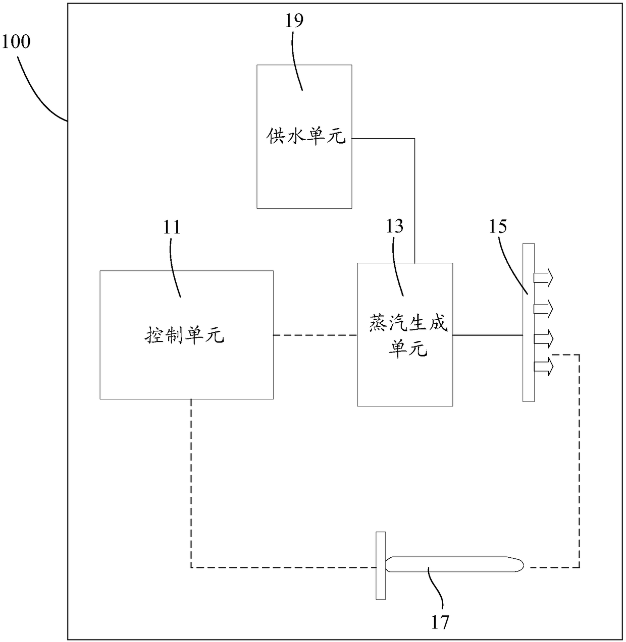
[0043] figure 2 The structural block diagram of the humidity control device provided for an embodiment of the present in


PUM


Abstract

The invention provides a humidity control device, a temperature control system of the humidity control device and a photolithography cabinet. Relative humidity of air provided by air conditioner equipment can be adjusted, normal work of production equipment is ensured, and the product yield is increased. The humidity control device comprises a control unit, a steam generation unit, a steam distribution unit and a monitoring unit. The monitoring unit is used for sending the humidity of air provided by the air conditioner equipment and provides the sensed humidity information of air for the control unit. The control unit is used for controlling the output state of the steam generation unit according to the received air humidity information, and therefore the steam amount of the water steam provided by the steam generation unit for the steam distribution unit is controlled. The steam distribution unit is used for providing the received water steam for the air conditioner equipment so thatthe water steam and air provided by the air conditioner equipment can be mixed.

Description


Claims


Application Information

Patent Timeline
Owner HUAIAN IMAGING DEVICE MFGR CORP
Why Eureka
Try Eureka