Clamping and hanging device for wing plate variable cross-section beam suspension

A technology of variable cross-section beams and wing plates, applied in bridges, bridge construction, erection/assembly of bridges, etc., can solve problems such as danger, precision-rolled threaded steel breakage, etc., and achieve convenient dismantling, local stress reduction, and strong applicability Effect

Pending Publication Date: 2018-07-20
THE 3RD ENG CO LTD OF CHINA RAILWAY 16TH BUREAU GRP CO LTD +1
View PDF0 Cites 0 Cited by
  • Summary
  • Abstract
  • Description
  • Claims
  • Application Information

AI Technical Summary

Benefits of technology

This new design allows for better control over how much weight it's carrying during flight without causing excessive bending or strain that could harm its components. It also makes installation easier because there are no wires attached between them instead of cables themselves. Overall, this technology improves stability while reducing risk from external forces such as wind pressure and vibrations.

Problems solved by technology

This patented technical problem addressed in this patents relates to improving safety during use of bridges constructed from segments made up of reinforced concrete materials such as prestressed tubular bars that support heavy loads over long distances without causing damage due to excessive bending stress caused by gravity waves passing along these sections.

Method used


Image

  • Clamping and hanging device for wing plate variable cross-section beam suspension
  • Clamping and hanging device for wing plate variable cross-section beam suspension
  • Clamping and hanging device for wing plate variable cross-section beam suspension

Examples


Embodiment Construction

[0037] The present invention will be described in further detail below in conjunction with the accompanying drawings.

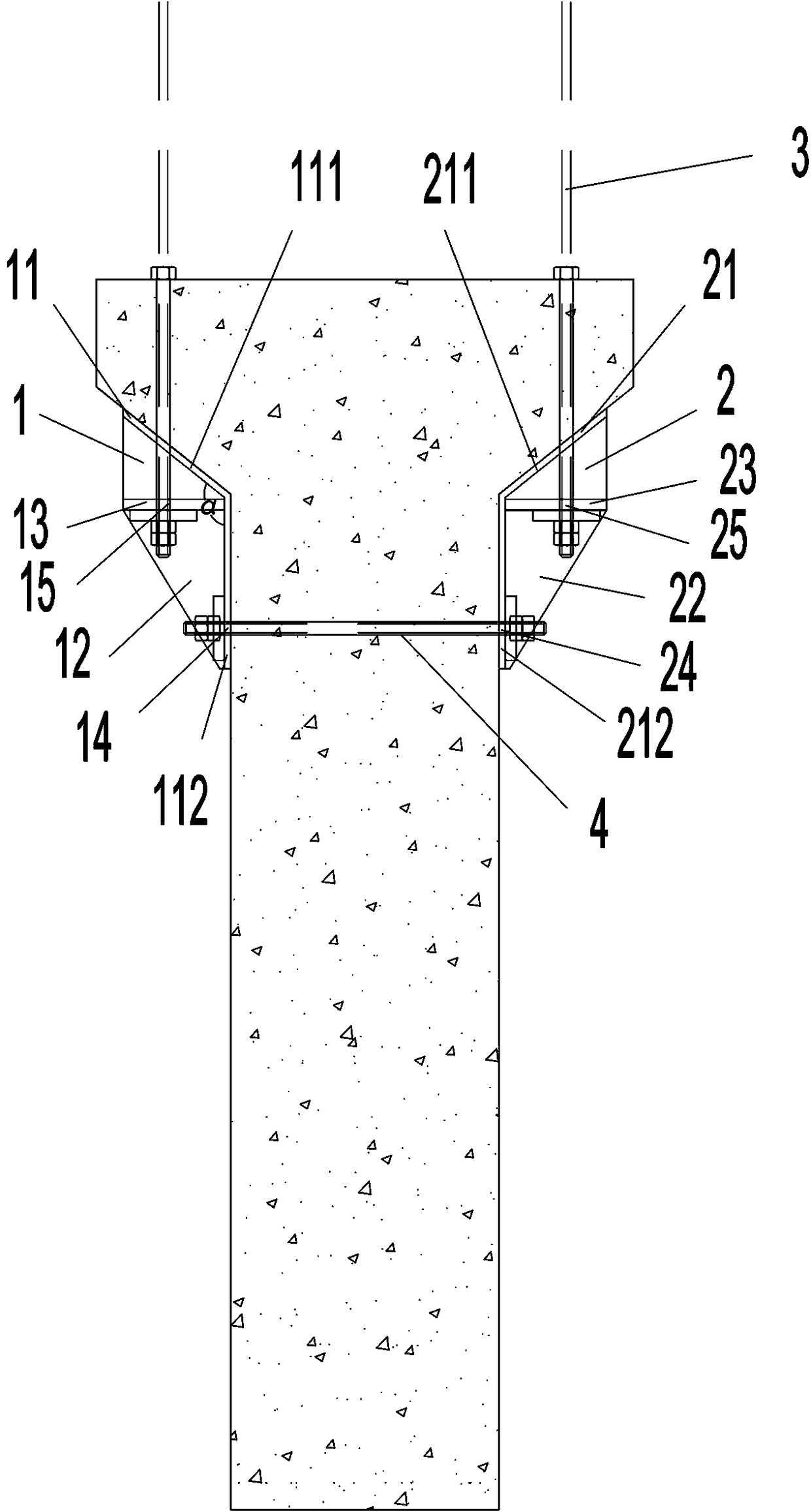
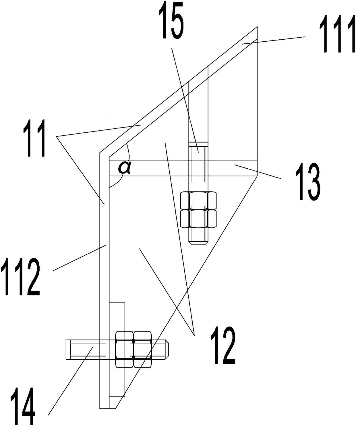
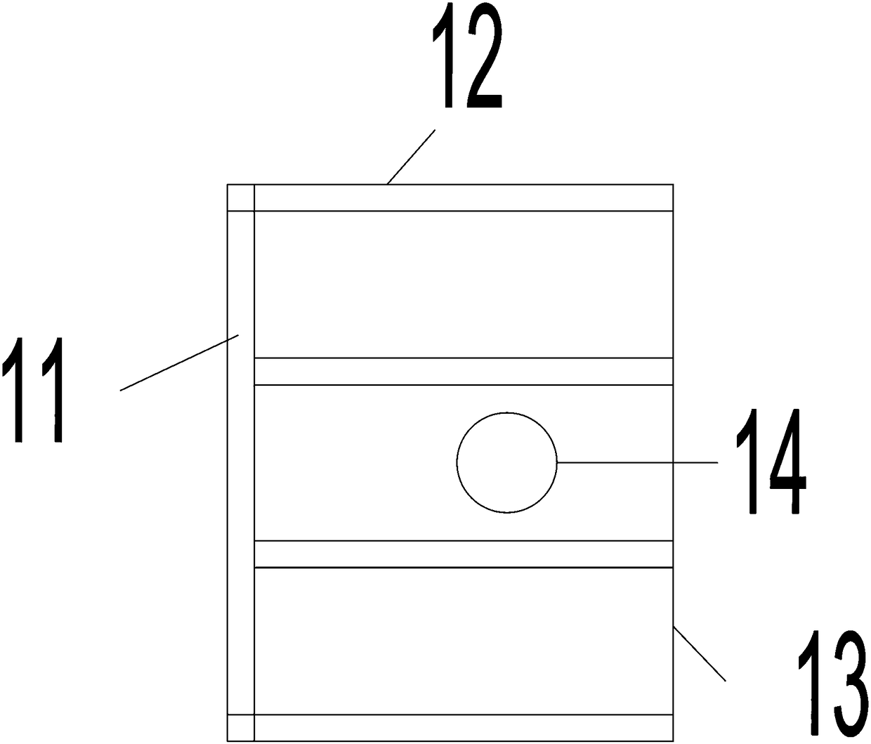
[0038] Such as figure 1 , 2 , 3 and 4, a clamping device for hanging a variable-section beam of a wing plate, is characterized in that: it includes a left clamping device 1 and a right clamping device 2 symmetrically placed on both sides of the turning point of the beam wing plate, and the left clamping device 2 The clamping and lifting device 1 includes a left sticking plate 11, a plurality of left ribs 12, a left support plate 13, a left reserved horizontal hole 14 and a left reserved vertical hole 15; the left sticking plate 11 includes at least two Composed of the first patch 111 and the second patch 112 at the corner, the angle α is greater than or equal to the turning angle of the beam wing, and the connection between the first patch 111 and the second patch 112 is fixed or integrated The left support plate 13 is molded, and the left support plate 13 is


PUM


Abstract

The invention relates to a clamping and hanging device for wing plate variable cross-section beam suspension. The clamping and hanging device for the wing plate variable cross-section beam suspensioncomprises a left clamping and hanging device and a right clamping and hanging device which are symmetrically placed on two sides of the turning point of a beam wing plate. The left clamping and hanging device comprises a left sticking plate, a plurality of left rib plates, a left supporting plate, a left reserved horizontal hole and a left reserved vertical hole. The left sticking plate comprisesat least a first sticking plate with an alpha angle and a second sticking plate with an alpha angle. The alpha angle is equal or greater than the turning angle of the beam wing plate. The connecting position of the first sticking plate and the second sticking plate is fixedly connected or integrated to form the left supporting plate. The upper and lower portions of the left supporting plate are connected with the first sticking plate and the second sticking plate through the left rib plates. The left reserved horizontal hole is formed in the second sticking plate. Friction force is generated in the way that two sides horizontally pass fining threaded steel bar through the reserved hole and a nut is screwed up to clamp a beam body to resist horizontal shear force of a hanger, and at the same time, the pre-tightening force and friction force are formed between the upper and lower nuts of the hanger, so that the horizontal shear force of the hanger is resisted doubly.

Description


Claims


Application Information

Patent Timeline
Owner THE 3RD ENG CO LTD OF CHINA RAILWAY 16TH BUREAU GRP CO LTD
Why Eureka
Try Eureka