Light sensor, light detecting method and display device

A light sensor and light detection technology, applied in the field of light detection, can solve the problems of small current signal, insignificant effect, large noise, etc., and achieve the effect of improving test accuracy

Active Publication Date: 2018-07-20
BOE TECH GRP CO LTD
View PDF6 Cites 6 Cited by
  • Summary
  • Abstract
  • Description
  • Claims
  • Application Information

AI Technical Summary

Benefits of technology

This patented technology uses an opto-electronic device called OpSensor (Optrolled Quantum Sensors) which can detect changes caused by external stimuli like pressure or temperature on small areas such as paper. By adjusting certain parameters for this purpose, it becomes possible to make precise measurements even with tiny sensory cells embedded within them.

Problems solved by technology

This patented technical problem addressed by this patents relates to improving detecting accuracy when combining charged particles with photons onto semiconductor devices such as photoelectric cells (PECs). Current methods often result in insufficient signals due to smaller currents caused by high temperature processes that can be very noisy during operation.

Method used


Image

  • Light sensor, light detecting method and display device
  • Light sensor, light detecting method and display device
  • Light sensor, light detecting method and display device

Examples


Embodiment Construction

[0040] In order to explain the present invention more clearly, the present invention will be further described below in conjunction with preferred embodiments and drawings. Similar components in the drawings are denoted by the same reference numerals. Those skilled in the art should understand that the content described below is illustrative rather than restrictive, and should not limit the protection scope of the present invention.

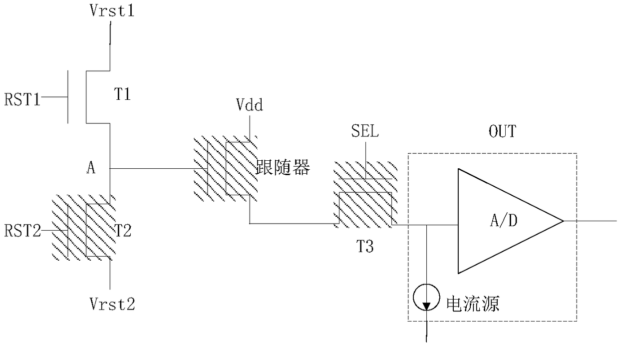
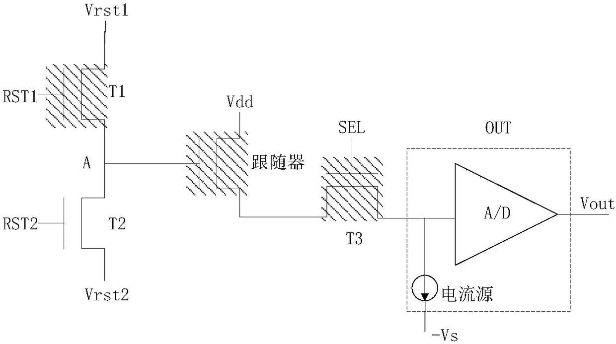
[0041] This embodiment provides a photosensor including: a first thin film transistor, a second thin film transistor, a voltage follower, a third thin film transistor, and an output unit, wherein the first end of the first thin film transistor, the second thin film transistor The first terminal of the transistor and the input terminal of the voltage follower are connected to the first node; the second terminal of the first thin film transistor receives a first level signal, and the second terminal of the second thin film transistor receives a second L


PUM


Abstract

The invention discloses a light sensor comprising first and second thin film transistors, a voltage follower, a third thin film transistor and an output unit. First ends of the first and second thin film transistors and an input end of the voltage follower are connected to a first node. One thin film transistor in the first thin film transistor and the second thin film transistor is switched on inresponse to a control signal thereof, the third thin film transistor obtains the following voltage of the first node through the voltage follower and transmits the following voltage to the output unit, and a first digital voltage is outputted after conversion. The other one of the thin film transistors receives illumination to generate a light leakage current to change a potential of the first node, the third thin film transistor obtains the following voltage of the first node through the voltage follower and transmits the following voltage to the output unit, and a second digital voltage isoutputted after conversion. An embodiment of the present invention provides the light sensor, a light detecting method and a display device, and a signal to noise ratio and test accuracy can be improved.

Description


Claims


Application Information

Patent Timeline
Owner BOE TECH GRP CO LTD
Why Eureka
Try Eureka