Glue injection plunger head and glue injection device

A technology of plunger and plug head, which is applied in the field of injection plunger head and injection device, which can solve problems such as waste of molten material, blockage of storage tank, and influence on product plasticization performance, so as to reduce leakage, improve utilization rate, Reducing the effect of backflow waste

Pending Publication Date: 2018-08-28
BORCH MACHINERY
View PDF0 Cites 0 Cited by
  • Summary
  • Abstract
  • Description
  • Claims
  • Application Information

AI Technical Summary

Benefits of technology

The technical effect of this new design is how it allows excessive liquid (molten) collateral fluid or other substances generated during manufacturing processes to recycle back into the process without causing damage or contamination. This helps save resources while improving production efficiency.

Problems solved by technology

The technical problem addressed in this patented text relates how to prevent leaks that occur during high-pressure injection processes caused by excessive meltdroplet movement within an injection plumping rod used with current systems due to poor sealing design on these parts.

Method used


Image

  • Glue injection plunger head and glue injection device
  • Glue injection plunger head and glue injection device
  • Glue injection plunger head and glue injection device

Examples


Embodiment Construction

[0022] The present invention will be further described below in conjunction with the accompanying drawings and specific implementation methods. It should be noted that, on the premise of no conflict, the various embodiments or technical features described below can be combined arbitrarily to form new embodiments.

[0023] In describing the present invention, it should be understood that the terms "central", "longitudinal", "transverse", "upper", "lower", "front", "rear", "left", "right", "horizontal ", "vertical", "top", "inner", "outer" and other indicated orientations or positional relationships are based on the orientations or positional relationships shown in the drawings, and are only for the convenience of describing the present invention and simplifying the description, rather than Nothing indicating or implying that a referenced device or element must have a particular orientation, be constructed, and operate in a particular orientation should therefore not be construed as


PUM


Abstract

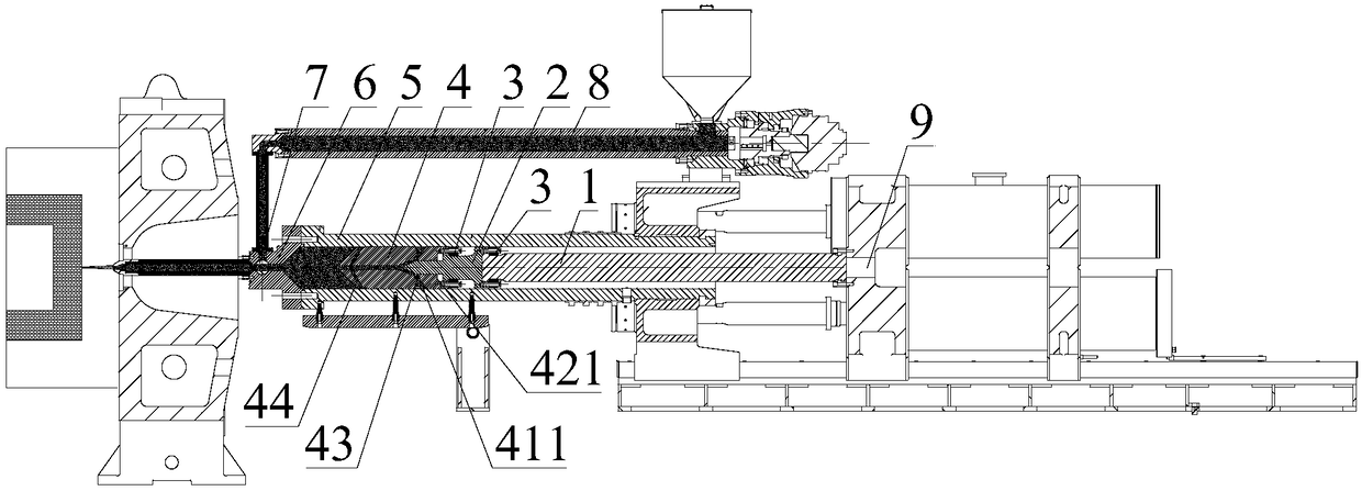
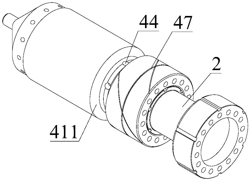
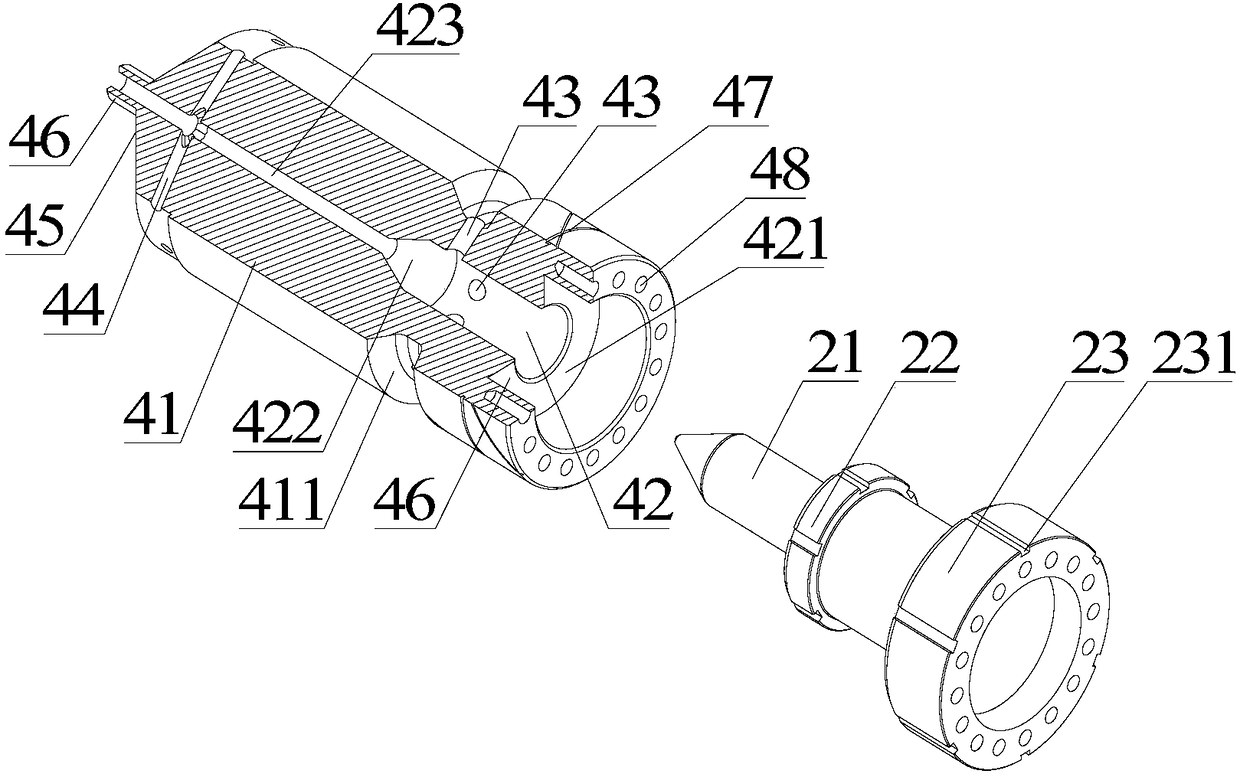
The invention discloses a glue injection plunger head and a glue injection device. The glue injection plunger head comprises a plunger main body part, wherein the outer peripheral wall of the plungermain body part is suitable for sliding fit with the inner peripheral wall of the material storage cylinder. An accommodating groove is arranged on the outer peripheral wall of the plunger main body part; the plunger body part is internally provided with a central hole and at least one first channel which is connected between the central hole and the accommodating groove; a moving plunger part, thefirst end of the moving plunger part is provided with a guide column extending into the central hole; the second end of the moving plunger part is adapted to be connected to a retractable plunger rod; a limit element arranged at one end of the plunger main body part, adjacent to the moving plunger part; the outer peripheral wall of the plunger main body part is provided with an air guide groove communicated with the accommodating groove. The glue injection plunger head can recover the molten colloid material leaked from the gap between the plunger head and the cylinder wall for secondary glueinjection, so that the leakage of the molten colloid material can be effectively reduced, and the utilization rate of the raw material is improved.

Description


Claims


Application Information

Patent Timeline
Owner BORCH MACHINERY
Why Eureka
Try Eureka