Salt bath furnace blanking device and salt bath heating furnace

A technology of blanking device and salt bath furnace, used in furnaces, heat treatment baths, heat treatment furnaces, etc., can solve problems such as affecting the quality of workpieces, poor quenching, and easily sticking materials, so as to ensure the quality of workpieces, avoid contact, and avoid poor quenching. Effect

Pending Publication Date: 2018-11-02
江苏丰东热技术有限公司
View PDF0 Cites 0 Cited by
  • Summary
  • Abstract
  • Description
  • Claims
  • Application Information

AI Technical Summary

Benefits of technology

This patented technology describes an improved system for cleanliness during manufacturing processes used in producing electronic devices such as semiconductors or displays. It includes two main components: one uses a special type of material called bakecloth that helps remove any impurities on surfaces being processed; another component involves a machine where tiny particles are removed from materials like silicone oil onto wafers before they enter them. These small particles help improve their performance and reduce damage caused when these products come off. Overall, this new method improves productivity while maintaining high levels of purity standards throughout production lines.

Problems solved by technology

This patents discusses how different types of materials may get stuck inside certain parts of a traditional type of hearth during use when melting salt liquids or another fluid called hot oil overcomes these issues with older methods such as sandwich blinds. Additionally, there have been attempts made to prevent damage caused by excessive pressure applied through the walls of the heartha's porcelain plate due to poor contact between them and the surrounding environment.

Method used


Image

  • Salt bath furnace blanking device and salt bath heating furnace
  • Salt bath furnace blanking device and salt bath heating furnace
  • Salt bath furnace blanking device and salt bath heating furnace

Examples


no. 1 example

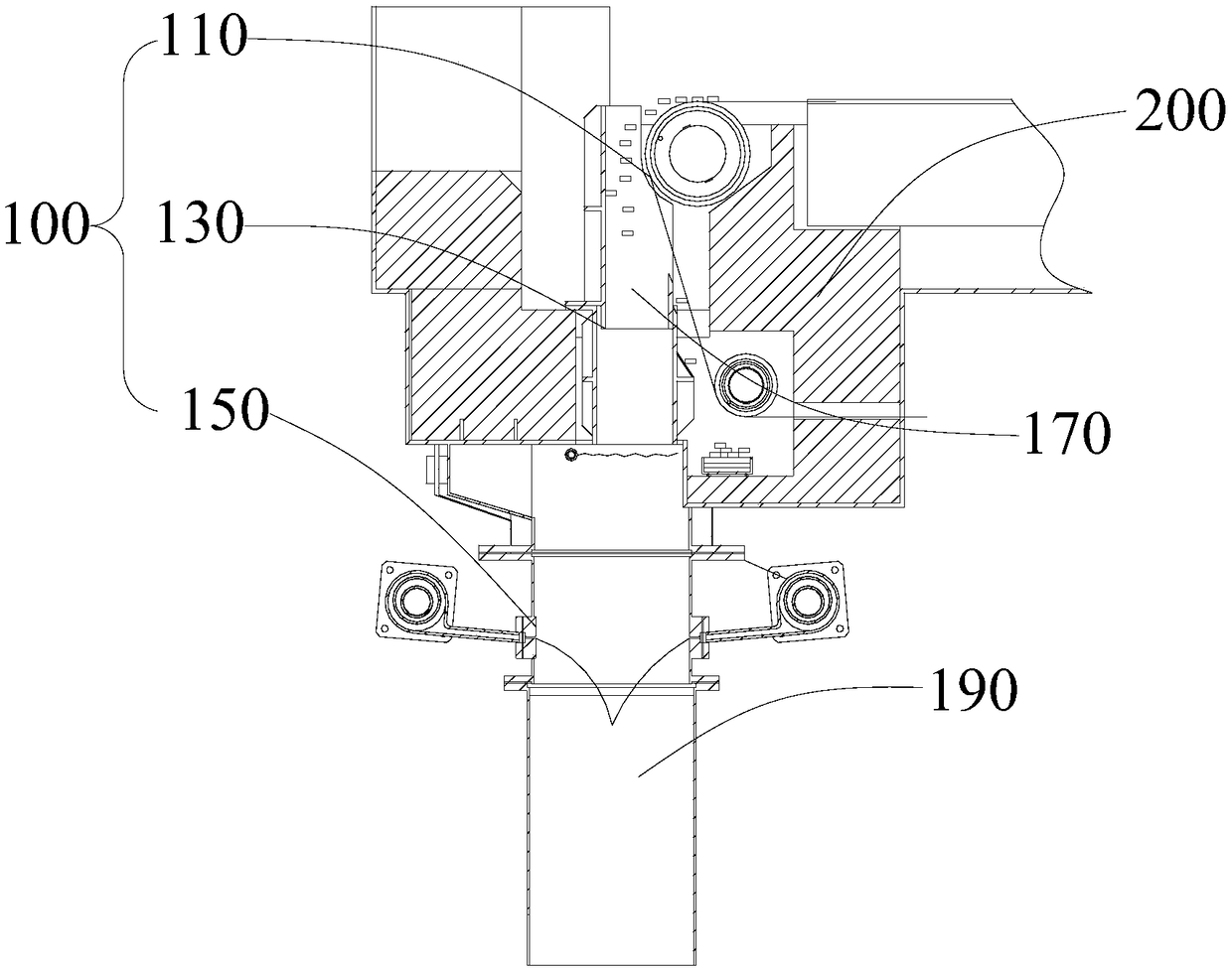
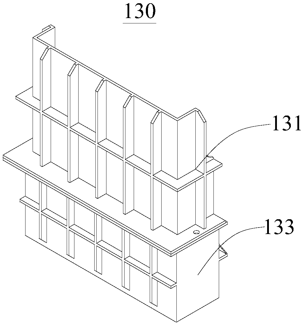
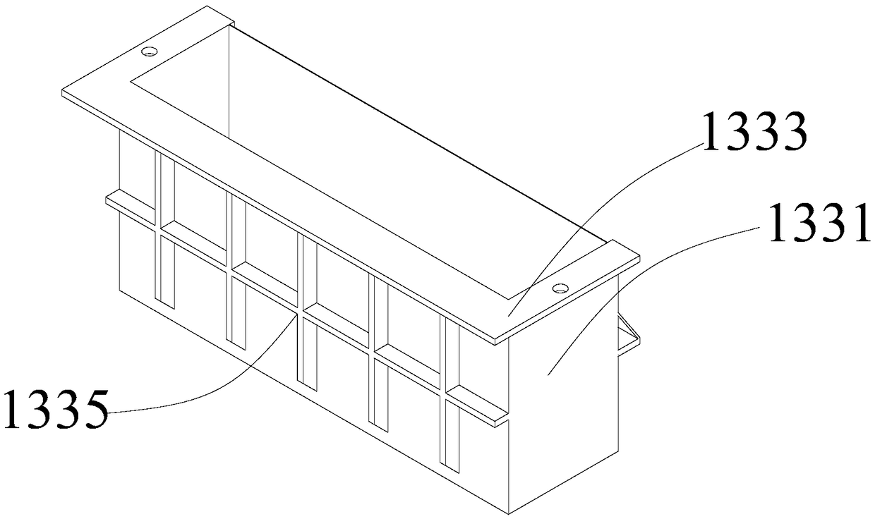
[0037] See figure 1 This embodiment provides a salt bath furnace blanking device 100, which is arranged in the heating furnace body 200. The heating furnace body 200 has a blanking port. The salt bath furnace blanking device 100 includes a workpiece conveying mechanism 110 and a workpiece blanking mechanism. 130 and the salt curtain blanking mechanism 150, the workpiece conveying mechanism 110 is used to be accommodated in the heating furnace body 200, and the workpiece conveying mechanism 110 has a discharge end corresponding to the blanking port, and the workpiece blanking mechanism 130 is used to be arranged in At the blanking port, and the workpiece blanking mechanism 130 has a first blanking channel 170 with a smooth inner wall. The top of the first blanking channel 170 is disposed opposite to the discharge end, and the salt curtain blanking mechanism 150 is used to be arranged at the blanking port The salt curtain blanking mechanism 150 has a second blanking channel 190, and

no. 2 example

[0052] See Figure 7 This embodiment provides a salt bath heating furnace 10, including a heating furnace body 200 and a salt bath furnace blanking device 100, wherein the basic structure and principle of the salt bath furnace blanking device 100 and the technical effects produced and the first implementation The examples are the same. For a brief description, for parts not mentioned in this embodiment, please refer to the corresponding content in the first embodiment.

[0053] The heating furnace body 200 has a blanking port. The salt bath furnace blanking device 100 includes a workpiece conveying mechanism 110, a workpiece blanking mechanism 130, and a salt curtain blanking mechanism 150. The workpiece conveying mechanism 110 has a discharge end corresponding to the blanking port. , The workpiece blanking mechanism 130 has a first blanking channel 170 with a smooth inner wall, and the top of the blanking channel is opposite to the discharge end. The salt curtain blanking mechanism


PUM


Abstract

Relating to the technical field of industrial furnace blanking, the invention provides a salt bath furnace blanking device and a salt bath heating furnace. The salt bath furnace blanking device comprises a workpiece conveying mechanism, a workpiece blanking mechanism and a salt curtain blanking mechanism. The workpiece conveying mechanism is accommodated in the heating furnace body, also has a discharge end corresponding to a blanking port, and has a first blanking passage with a smooth inner wall, the top of the first blanking passage and the discharge end are disposed oppositely, the salt curtain blanking mechanism is disposed below the blanking port, and has a second blanking passage, and the second blanking passage and the first blanking passage are disposed oppositely and are communicated with each other. Compared with the prior art, the salt bath furnace blanking device provided by the invention avoids contact of workpieces with furnace bricks, and then avoids material sticking phenomenon, enables workpieces to fall into brine smoothly, avoids "poor quenching" phenomenon, and ensures the workpiece quality.

Description


Claims


Application Information

Patent Timeline
Owner 江苏丰东热技术有限公司
Why Eureka
Try Eureka