Dual-groove microstrip antenna

A technology of microstrip antenna and double groove, which is applied in the direction of antenna, antenna grounding device, radiating element structure, etc., can solve the problems of ultra-wideband antenna work interference, etc., and achieve the effect of low cost, simple manufacture, and easy integration

Inactive Publication Date: 2018-12-11
CHINA JILIANG UNIV
View PDF3 Cites 2 Cited by
  • Summary
  • Abstract
  • Description
  • Claims
  • Application Information

AI Technical Summary

Problems solved by technology

The existence of these narrowband communication systems will cause certain interference to the work of UWB antennas

Method used


Image

  • Dual-groove microstrip antenna
  • Dual-groove microstrip antenna
  • Dual-groove microstrip antenna

Examples


Embodiment 1

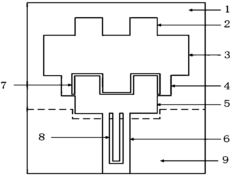
[0022] Dual Groove Microstrip Antenna:

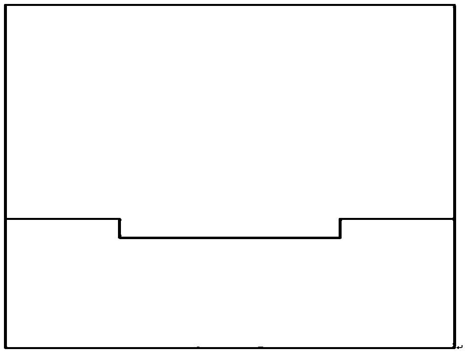
[0023] FR-4 with a relative permittivity of 4.4 is selected as the substrate of the double-groove microstrip antenna. The length of the substrate is 33mm, the width is 32mm, and the thickness is 1.5mm. The overall length of the metal grounding piece is 32mm and the width is 11mm, and the length of the defective part of the metal grounding piece is 11mm and the width is 1mm. The rectangle group is composed of two identical rectangles, and the two identical rectangles are symmetrically distributed above the first rectangle, each of which has a length of 4.0 mm and a width of 3.8 mm. The first rectangle has a length of 21mm and a width of 8mm. The second rectangle has a length of 17mm and a width of 4.15mm. The length of the two-stage stepped grooves is 5 mm, and the groove width is 0.5 mm. The third rectangle has a length of 10 mm and a width of 2.7 mm. The feed microstrip line has a length of 12mm and a width of 4mm. The length of b...


PUM

PropertyMeasurementUnit
Lengthaaaaaaaaaa
Widthaaaaaaaaaa
Thicknessaaaaaaaaaa

Abstract

The invention discloses a dual-groove microstrip antenna. The antenna includesa substrate, metal grounding strip, a group of rectangles below which is a first rectangle, Below the first rectangle is asecond rectangle, a two-step groove is hollowed out in the second rectangle, below the second rectangle is a third rectangle, below the third rectangle is a feeding microstrip line, a U-shaped grooveis hollowed out in the feeding microstrip line, the antenna is integrally symmetrical, and the double groove structure enables the antenna to be at 3.3 GHz- 3.8 GHz and 5.2 GHz- 5.7 GHz two frequencyband work effectively and suppresses interference of two different narrowband communication system. The FR-4 is adopted as a substrate, that material has the advantage of small volume, simple fabrication, easy integration with the RF front end, good radiation characteristics, low cost, and the like.

Description

technical field [0001] The present invention relates to antennas, in particular to double-groove microstrip antennas. Background technique [0002] UWB wireless technology has a transformative effect on the further development of wireless communication. In recent years, antennas have been rapidly developed in civilian use. In wireless application principles, antennas radiate electromagnetic energy to other hardware in the system. In the transmission process of the ultra-wideband antenna, when the transmission signal received by the ultra-wideband antenna is transmitted as the receiving antenna, the radiation injection of the electromagnetic energy received by the ultra-wideband antenna is completed, and it is provided to the RF receiver part for effective use. . In recent years, research on antennas has become an upsurge among researchers, and they are used in radars, radio stations, detectors, walkie-talkies, wireless local area networks, mobile phones, remote control dev...

Claims


Application Information

Patent Timeline
IPC IPC(8): H01Q1/36H01Q1/48H01Q13/08
CPCH01Q1/36H01Q1/48H01Q13/08
Inventor 李绍和李九生
Owner CHINA JILIANG UNIV
Why Eureka
Try Eureka