Jet mill for ultra-fine powder

A technology of jet mill and ultrafine powder, which is applied in grain processing and other directions, can solve the problems that materials cannot meet the requirements of microgrinding and ultrafine powder, cannot adapt to cutting-edge national defense, high technology, etc., and achieve the effect of meeting processing requirements and adapting to technological development

Inactive Publication Date: 2019-01-04
WUXI PROFESSIONAL COLLEGE OF SCI & TECH
View PDF3 Cites 0 Cited by
  • Summary
  • Abstract
  • Description
  • Claims
  • Application Information

AI Technical Summary

Benefits of technology

This technology helps improve the separation efficiency for different types of granular or solid waste materials during recycling processes. It uses an oscillator called a spray gun connected between two pipes filled with liquid (powders) before they enter the machine's feed channels. By injecting compressed gas onto these droplets at high velocity, it causes them to break apart and separate larger pieces of waste. These smaller fragments may also pass downstream without being further processed. Overall, this technology improves efficient sorting techniques used in various industries such as manufacturing industry.

Problems solved by technology

This patented technical problem addressed in this patent relates to improving the quality control standards needed when producing small amounts of material used in various industries like military applications where strict limits on contaminant levels can affect performance. Current methods require expensive equipment which may result in unclean surfaces due to imperfections during production processes.

Method used


Image

  • Jet mill for ultra-fine powder
  • Jet mill for ultra-fine powder
  • Jet mill for ultra-fine powder

Examples


Embodiment Construction

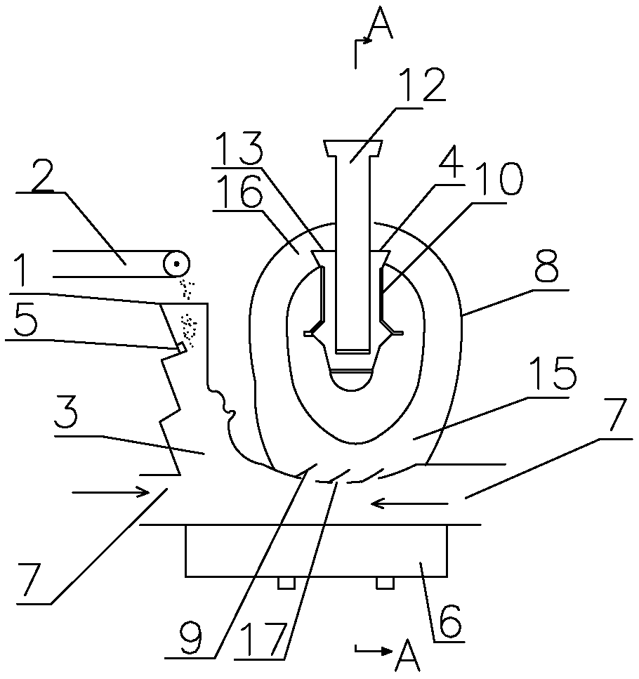
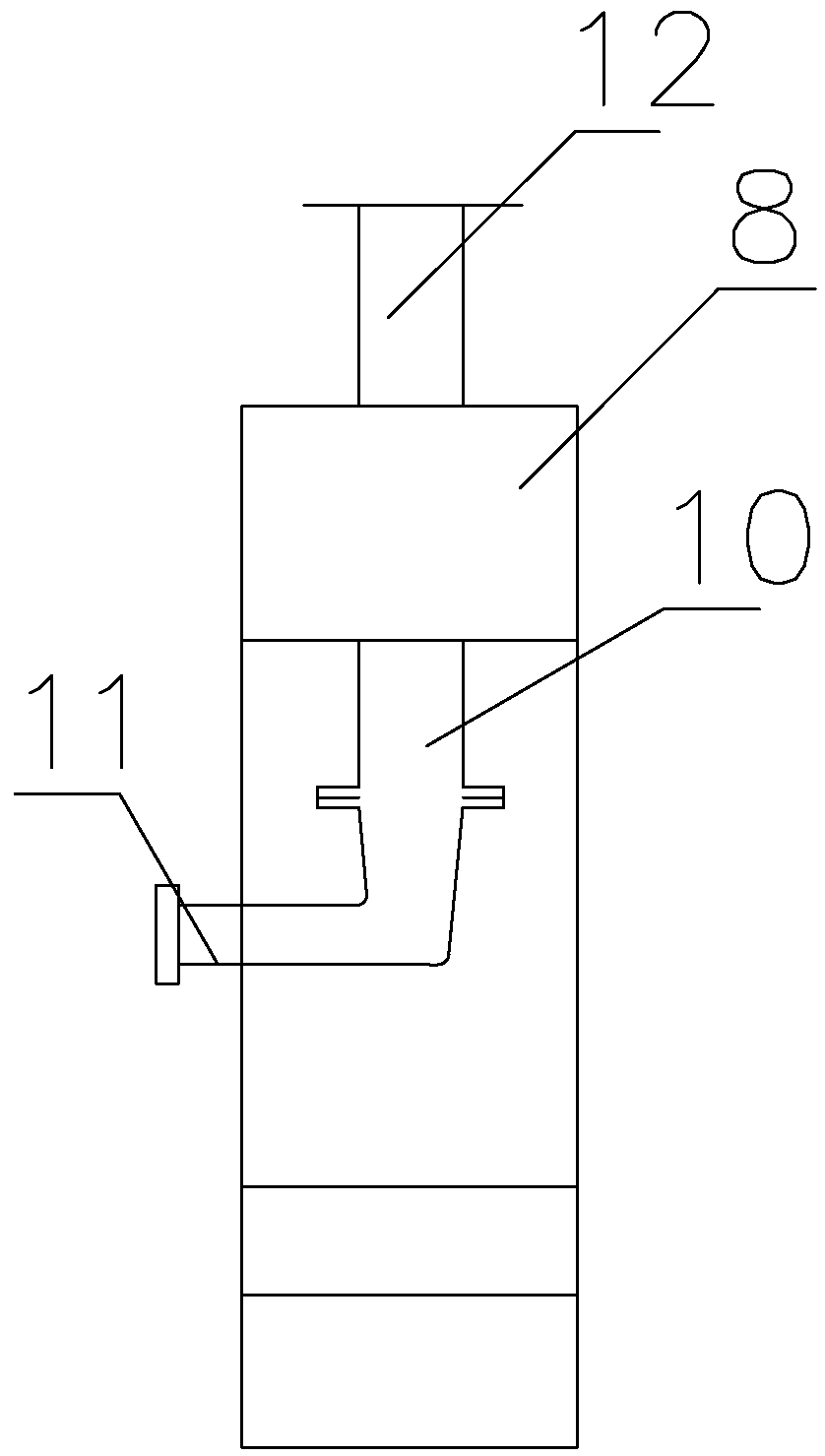
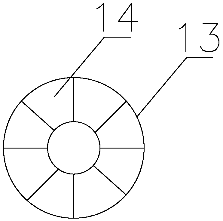
[0013] Such as figure 1 , figure 2 , image 3 As shown, the present invention comprises a hopper 1, a feeder 2, a crushing device, and a classifying device. The hopper 1 is connected with the crushing device through a feedway 3, and the classifying device includes a classifier 4. The entrance of the feedway 3 is provided with an injector 5, and the feedway 3. The bottom is connected with a support box 6, and the support box 6 is provided with an air flow port 7. The crushing device includes a variable-section circulation pipe 8 connected with the material channel 3 and located above the support box 6, and a variable-section circulation tube connected to the material channel 3. The pipe 8 is provided with a nozzle 9, the axis of the spraying direction of the nozzle 9 is tangent to the center line of the variable cross-section circulation pipe 8, and the upper part of the variable cross-section circulation pipe 8 is connected with the classifier 4, and the classifier 4 is connect


PUM


Abstract

The invention provides a jet mill for ultra-fine powder. The jet mill for ultra-fine powder can meet requirements of processing of multiple materials, fine pulverization is realized, and thus, the jetmill for the ultra-fine powder effectively adapts to technical development. The jet mill for the ultra-fine powder comprises a hopper, a charging device, a pulverizing device and a classifying device, wherein the hopper is connected with the pulverizing device via a channel; the classifying device comprises a classifier; an ejector is arranged at the inlet of the channel; the bottom of the channel communicates with a supporting box; an airflow opening is formed in the supporting box; the pulverizing device comprises variable-cross-section circulating tube which communicates with the channel and is positioned above the supporting box; a nozzle is arranged on the portion, which is connected with the channel, of the variable-cross-section circulating tube; the axis of a nozzle blowing direction is tangential to the central line of the variable-cross-section circulating tube; the upper portion of the variable-cross-section circulating tube communicates with a classifier; the classifier isconnected with an inner tube; and a discharging opening is formed in the inner tube.

Description


Claims


Application Information

Patent Timeline
Owner WUXI PROFESSIONAL COLLEGE OF SCI & TECH
Why Eureka
Try Eureka