A shock absorber for automobile seats

A technology of shock absorbing device and car seat, which is applied in the direction of seat suspension device, etc., can solve the problems that the shock absorbing device is not suitable for large-scale popularization and application, the shock absorbing effect is general, and the structure is complicated, and the shock absorbing effect is obvious, Guaranteed shock absorption effect and simple structure

Inactive Publication Date: 2019-01-15
陈沛
View PDF0 Cites 0 Cited by
  • Summary
  • Abstract
  • Description
  • Claims
  • Application Information

AI Technical Summary

Benefits of technology

This new design allows for better comfort by reducing impacts from cars' movements caused by road or traffic conditions while still maintain stability. It includes an elastic member made up of metal tubes connected between supports called legs placed at different points along its length. When there occurs sudden acceleration or deceleration, springs help absorb this energy without causing damage. A buffer material helps prevent tilting over time due to gravity. Overall, these technical features improve safety performance and durability of vehicle chairs.

Problems solved by technology

This patented technical problem addressed by this patents relates to reducing impact felt when an object moves around while being supported with its own weight. Existing solutions involve adding extra components like rubbing materials between support members that help prevent them from getting stuck together too much due to gravity forces caused by their movement. However these existing methods have limitations because they require multiple spring systems each time there needs to work properly. Additionally, current designs can easily get bent over if subjected to excessive force causing failure.

Method used


Image

  • A shock absorber for automobile seats
  • A shock absorber for automobile seats
  • A shock absorber for automobile seats

Examples


Embodiment Construction

[0019] The preferred embodiments of the present invention will be described in detail below in conjunction with the accompanying drawings, so that the advantages and features of the present invention can be more easily understood by those skilled in the art, so as to define the protection scope of the present invention more clearly.

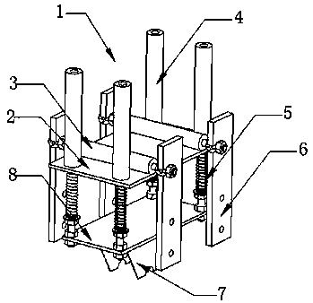
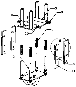
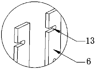
[0020] Such as Figure 1 to Figure 5 As shown, the shock absorbing device 1 includes a support plate 2 arranged horizontally, a support column 4 is provided above the four corners of the support plate 2, and two fixed cylinders 3 are arranged on the inner side of the support column 4. Both ends of the cylinder 3 are provided with a screw rod 10, and one end of each screw rod 10 is clamped with a baffle plate 6, and the upper part of each baffle plate 6 is provided with a bayonet 13, and the side of the baffle plate 6 is provided with several Round hole 11, a base device 12 is installed below the support plate 2, a base plate 8 is installed on the bo


PUM


Abstract

The invention discloses a shock absorber for automobile seats, comprising a horizontally arranged support plate; a support column is arranged above each of the four corners of the support plate, the inner side of each support column is provided with two fixed columns, both ends of the two fixed columns are provided with a screw rod, one end of each screw rod is clamped with a baffle plate, A basedevice is installed under the support plate, the lower part of the base device is provided with a bottom plate, a support bar is arranged above the four corners of the bottom plate, the upper part ofeach of the support bars penetrates the support plate, and the support bars are connected with the support columns; an outer part of each of the support bars is sleeved with a spring; a lower part ofthe support bars penetrates the bottom plate; and a bottom part of the support bars is sleeved with a second nut. Through the support column to support the automobile seat, the spring sleeved with thesupport bar can effectively reduce the vibration amplitude of the seat, thereby reducing the vibration feeling.

Description


Claims


Application Information

Patent Timeline
Owner 陈沛
Why Eureka
Try Eureka