Heating and evaporation device for feeding of uranium enrichment plant

A technology for heating evaporation and enrichment plants, applied in the field of uranium enrichment, which can solve the problems of setting too many feeding device points, occupying the feeding device for a long time, and not being able to realize online monitoring, so as to achieve improved intrinsic safety and low manufacturing cost , The effect of saving equipment investment

Inactive Publication Date: 2019-01-25
中核第七研究设计院有限公司
View PDF5 Cites 2 Cited by
  • Summary
  • Abstract
  • Description
  • Claims
  • Application Information

AI Technical Summary

Benefits of technology

This patented technology describes a new type of apparatus called a DSC (Digital Temperature Sensor). It uses two different types of sensors: one detects temperature on top or bottom of the materials being fed through pipes while another measures their temperatures at other locations along its length. These measurements are then transmitted wirelessly back to a central computer server where they are analyzed to determine if there're any problems related to excessive temperature or loadings during production processes. Additionally, this allows for efficient use of energy resources without causing unsafe situations like explosions due to high levels of oxygen inside the reactor tank. Overall, these technical improvements improve the efficiency and security of the thermal management systems within nuclear power plants.

Problems solved by technology

This patented technical problem addressed in this patents relates to improving the security for handling nuclear materials during storage at home without exposure risks such as radiation contamination from equipment that uses strong chemicals like radon (Ra).

Method used


Image

  • Heating and evaporation device for feeding of uranium enrichment plant
  • Heating and evaporation device for feeding of uranium enrichment plant
  • Heating and evaporation device for feeding of uranium enrichment plant

Examples


Embodiment Construction

[0043] The present invention will be described in further detail below in conjunction with the accompanying drawings and specific embodiments.

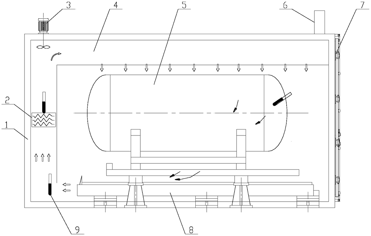
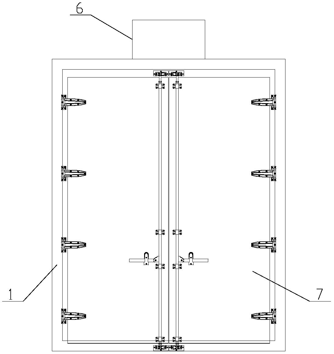
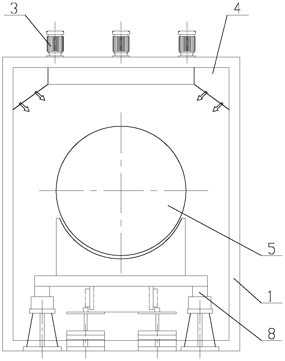
[0044] Such as Figure 1~3 A heating and evaporating device for feeding materials in a uranium enrichment plant shown, including a box body 1, an electric heater 2, a circulating fan 3, an air duct 4, a feeding container 5, an LED display screen 6, a gate 7, containers and rail supports Component 8, temperature detection instrument 9 and DCS system.

[0045] The box body 1 is a cuboid structure with a lateral width greater than its longitudinal height and can be used in conjunction with rail transport vehicles in uranium enrichment plants. The box body 1 is formed by splicing insulation material boards.

[0046] The feed container 5 is a cylindrical cavity structure, which is arranged inside the box body 1. The central axis of the feed container 5 is parallel to the transverse axis of the box body 1, and the central axis of the feed co


PUM


Abstract

The invention belongs to the technical field of uranium enrichment and discloses a heating and evaporation device for the feeding of a uranium enrichment plant. According to the heating and evaporation device of the invention, air in an air duct is heated through an electric heater; being stirred by a circulation fan, the hot air is blown into a box body through the air outlet of the air duct, sothat to a feeding container can be uniformly heated; a material in the feeding container is heated and sublimated into a gaseous-state material, and then the gaseous-state material is fed to a cascaded system, and at the same time, the air in the box body enters through the air inlet of the air duct; and therefore, the heating cycle of the hot air can be completed. The device of the invention hasthe advantages of simplicity, low manufacturing cost and convenient operation. With the heating and evaporation device adopted, the area of the plant and equipment investment can be saved.

Description


Claims


Application Information

Patent Timeline
Owner 中核第七研究设计院有限公司
Why Eureka
Try Eureka