Detachable U-shaped bolt
A bolt and U-shaped technology, applied in the direction of bolts, screws, nuts, etc., can solve the problems of troublesome use, adjustment of shape and length, single fixed structure, etc., and achieve the effect of flexible and convenient use and avoid loosening
- Summary
- Abstract
- Description
- Claims
- Application Information
AI Technical Summary
Problems solved by technology
Method used
Image

Examples
Example Embodiment
[0022] Example one:
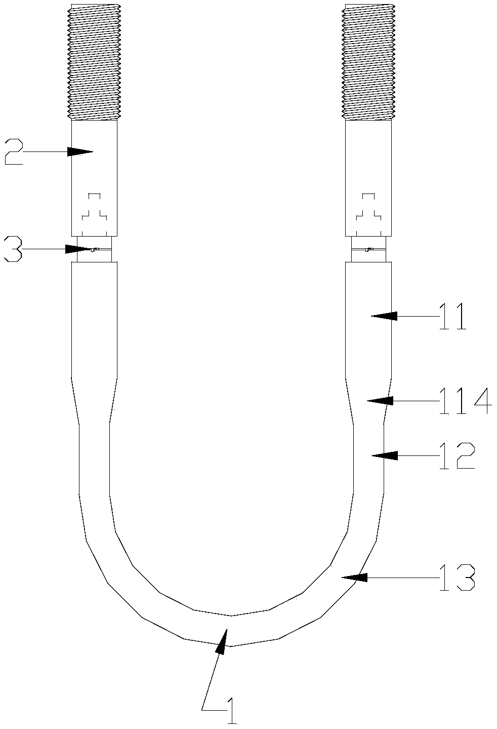
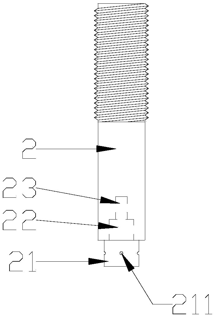
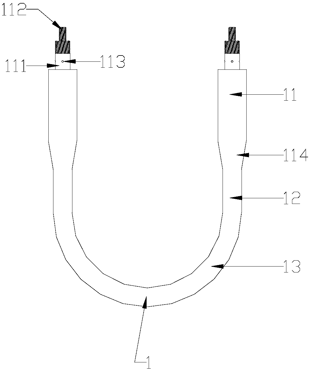
[0023] When the curvature of the top surface of the object to be fixed is large, the connecting rod 13 is selected as the bending rod 1 with a semicircular structure. Then, a certain length of extension rod 2 is selected according to the height of the object to be fixed, and then the second part of the bending rod 1 is selected. A connecting section 111 and a second connecting section 112 are screwed into the first threaded hole 22 and the second threaded hole 23 of the extension rod 2, and then the wire 3 is passed through the first through hole 113 and the second through hole 211 and punched Fasten the knot, and then use the spliced U-shaped bolts as required.
Example Embodiment
[0024] Embodiment two:
[0025] When the curvature of the top surface of the object to be fixed is small, the connecting rod 13 is selected as the crescent-shaped bending rod 1, and the following steps are the same as in the first embodiment.
Example Embodiment
[0026] Embodiment three:
[0027] When the top surface of the object to be fixed is a right-angled plane, the connecting rod 13 is selected as the bending rod 1 with a right-angle structure, and the following steps are the same as in the first embodiment.
[0028] According to the present invention, suitable bending rods and extension rods can be selected according to the height and top surface shape of the object to be fixed, and the bending rod and extension rod can be extended and bent through the first connecting section, the second connecting section, the first threaded hole and the second threaded hole. In the rod threaded connection, the position of the first connecting section and the third connecting section is defined by the metal wire fixed in the first through hole and the second through hole, so as to avoid looseness caused by relative rotation thereof, and is flexible and convenient to use.
PUM
 Abstract
Description
Claims
Application Information
 - R&D Engineer
- R&D Manager
- IP Professional
- Industry Leading Data Capabilities
- Powerful AI technology
- Patent DNA Extraction
Browse by: Latest US Patents, China's latest patents, Technical Efficacy Thesaurus, Application Domain, Technology Topic.
© 2024 PatSnap. All rights reserved.Legal|Privacy policy|Modern Slavery Act Transparency Statement|Sitemap