Rare earth mining crushed stone collecting device
A collection device and crushed stone technology, which is applied in the field of mining equipment, can solve the problems of low collection efficiency, inability to adapt, and unclean scraping, and achieve the effects of improving collection efficiency, labor-saving and convenient operation, and easy adjustment.
- Summary
- Abstract
- Description
- Claims
- Application Information
AI Technical Summary
Problems solved by technology
Method used
Image

Examples
Example Embodiment
[0036] Example 1
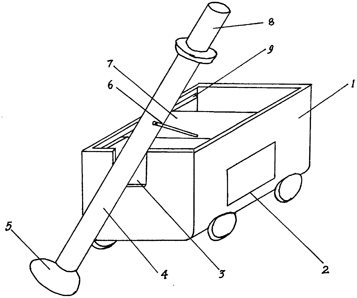
[0037] Such as Figure 1~3 As shown in 5, a rare earth mining crushed stone collection device of the present invention includes a screw conveyor and a transport vehicle 1.
[0038] The transport vehicle 1 is a box structure with an open top. The bottom of the transport vehicle 1 is provided with wheels. The right side wall of the transport vehicle 1 is provided with a discharge port. The discharge port is hinged with a discharge door 2 for easy access The gravel of the transport vehicle 1 is cleaned out; the left and right inner side walls of the transport vehicle 1 are provided with symmetrical slide grooves 9 in which a supporting plate 7 is arranged, and the upper surface of the supporting plate 7 is arranged in the middle position There is a set of support frames 6 inclined upward. One end of the support frame 6 is fixedly arranged on the supporting plate 7, and the other end is movably arranged on a screw conveyor. The movable connection can be hinged; in this
Example Embodiment
[0042] Example 2
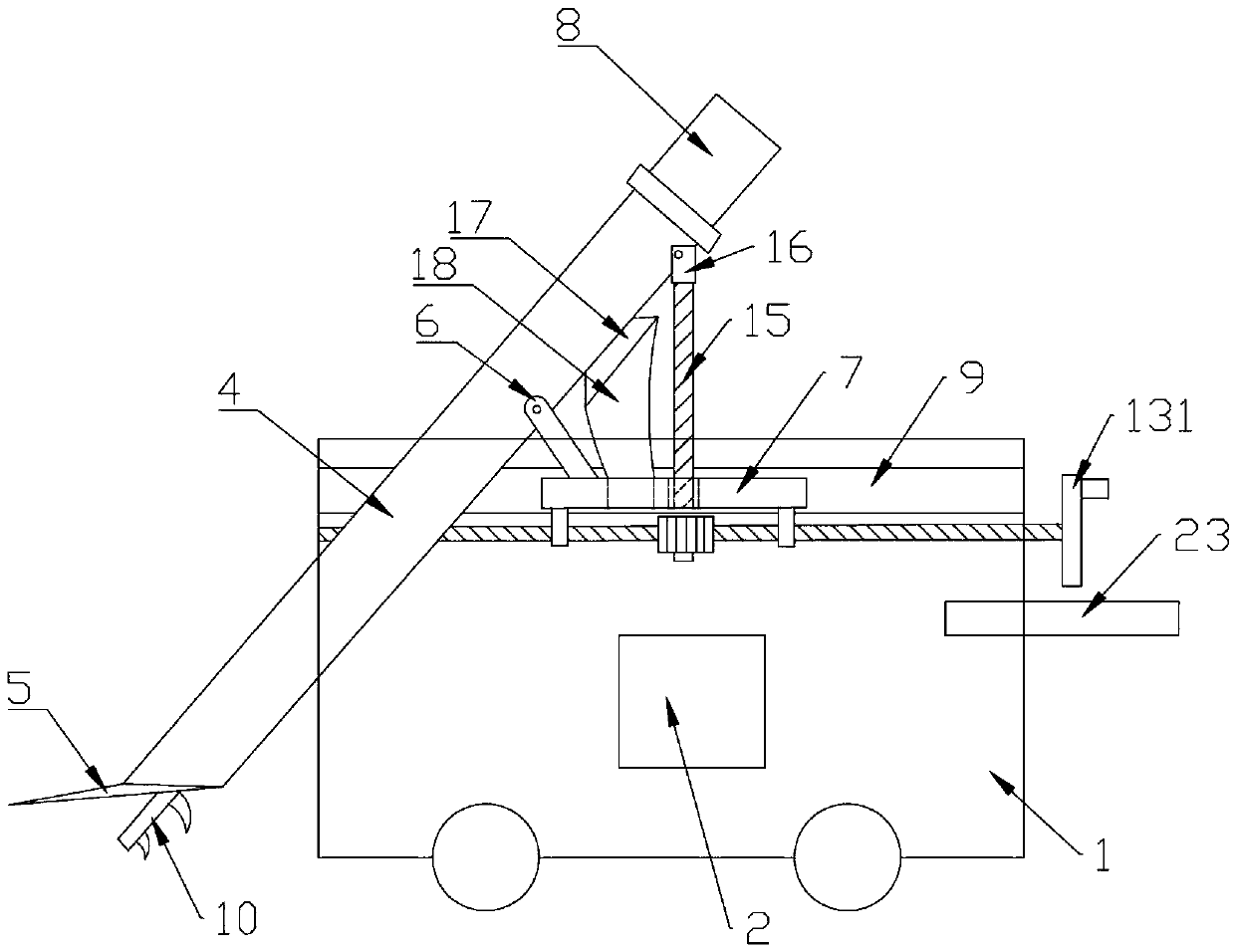
[0043] Such as Figure 4 As shown, this embodiment changes the turntable 131 to a drive motor 132 on the basis of the embodiment 1. The drive motor 132 is fixedly arranged outside the transport vehicle 1 and connected to the power source; the first screw rod 11 is connected through a coupling The driver 24 is connected to the output shaft of the driving motor 132, so that the driving motor 132 drives the first screw 11 to rotate. The driving motor 132 is used to drive the first screw 11 to rotate without manual rotation, which is more efficient and saves effort.
Example Embodiment
[0044] Example 3
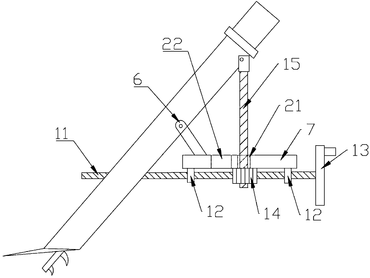
[0045] Such as Figure 1~7 As shown, this embodiment adds a second screw 15 and a worm wheel 14 on the basis of embodiment 1. Specifically, the device further includes a second screw 15 and a worm wheel 14; the supporting plate 7 is also provided with a second screw A perforation 20. In this embodiment, the first perforation 20 is located behind the second perforation 22; a cylindrical protrusion 19 is fixedly connected to the worm wheel 14, and the protrusion 19 is rotatably connected in the first perforation 20, The worm wheel 14 is located below the supporting plate 7, and the worm wheel 14 is located between the two nuts 12. The worm wheel 14 is arranged in parallel with the first screw 11, and the external gear of the worm wheel 14 meshes with the thread on the first screw 11 to form a worm gear mechanism.
[0046] Both the worm wheel 14 and the boss 19 are provided with a penetrating screw hole 21, the second screw 15 is threadedly connected in the screw hol
PUM
 Abstract
Description
Claims
Application Information
 - R&D Engineer
- R&D Manager
- IP Professional
- Industry Leading Data Capabilities
- Powerful AI technology
- Patent DNA Extraction
Browse by: Latest US Patents, China's latest patents, Technical Efficacy Thesaurus, Application Domain, Technology Topic.
© 2024 PatSnap. All rights reserved.Legal|Privacy policy|Modern Slavery Act Transparency Statement|Sitemap