Low-temperature waste heat utilization system

A low-temperature waste heat and low-temperature flue gas technology, applied in indirect heat exchangers, greenhouse gas reduction, lighting and heating equipment, etc. consumption effect

Pending Publication Date: 2019-06-28
SHENZHEN AUTO-UNION CONTROL SYST CO LTD
View PDF0 Cites 2 Cited by
  • Summary
  • Abstract
  • Description
  • Claims
  • Application Information

AI Technical Summary

Problems solved by technology

[0004] The purpose of the present invention is to provide a low-temperature waste heat utilization system, which aims to solve the technic

Method used


Image

  • Low-temperature waste heat utilization system

Examples


Embodiment Construction

[0033] Embodiments of the present invention are described in detail below, examples of which are shown in the drawings, wherein the same or similar reference numerals designate the same or similar elements or elements having the same or similar functions throughout. Attached below by reference figure 1 The described embodiments are exemplary and are intended to explain the present invention, but should not be construed as limiting the present invention.

[0034] In describing the present invention, it should be understood that the terms "length", "width", "upper", "lower", "front", "rear", "left", "right", "vertical", The orientation or positional relationship indicated by "horizontal", "top", "bottom", "inner", "outer", etc. are based on the orientation or positional relationship shown in the drawings, and are only for the convenience of describing the present invention and simplifying the description, rather than Nothing indicating or implying that a referenced device or eleme


PUM


Abstract

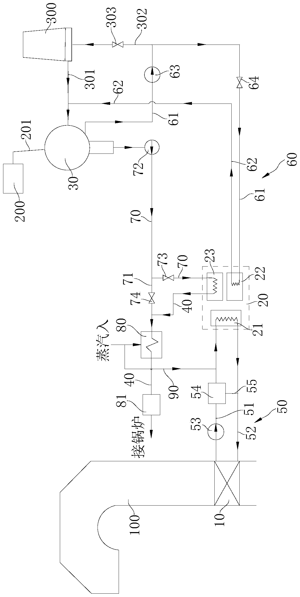
The invention belongs to the technical field of energy utilization equipment, in particular to a low-temperature waste heat utilization system. The system includes an absorbing-type heat pump, a low-temperature flue gas heat exchanger and a steam condenser, a generator, an evaporator and a condenser are arranged in the absorbing-type heat pump, a condensate outlet of the condenser communicates with a water inlet of a boiler, the low-temperature flue gas heat exchanger is connected with a flue way of the boiler, and a hot water outlet of the low-temperature flue gas heat exchanger is connectedwith a hot water inlet of a generator; and the steam condenser is connected with a gas exhaust pipeline of a steam turbine, a cooling water outlet of the steam condenser is connected with a cooling water inlet of the evaporator, and a condensate outlet of the steam condenser is connected with a condensate inlet of the condenser. The waste heat utilization system can reasonably utilize the low-temperature flue gas waste heat and the waste heat produced by the cooling circulating water, and the condensate is supplied to the boiler by using the waste heat after heating, so that the low-quality waste heat in the industrial production is continuously converted into the useful energy of the production system, and the heat loss during industrial production is reduced advantageously.

Description


Claims


Application Information

Patent Timeline
Owner SHENZHEN AUTO-UNION CONTROL SYST CO LTD
Why Eureka
Try Eureka