Photoetching system and photoetching method thereof

A lithography system and lithography technology, applied in micro-lithography exposure equipment, optics, optomechanical equipment, etc., to achieve the effect of mass production of wafers, flexible lithography system, and avoiding equipment damage

Active Publication Date: 2019-07-05
CHANGXIN MEMORY TECH INC
View PDF9 Cites 0 Cited by
  • Summary
  • Abstract
  • Description
  • Claims
  • Application Information

AI Technical Summary

Benefits of technology

This technology allows for flexibility when switching between different types or stages within an integrated circuit manufacturing process without interrupting its operation. It uses multiple production facilities that are controlled together like a scheduler, allowing them to work alongside each others' capabilities while still being efficient at producing high-quality wafers. Additionally, this design helps prevent failures from happening during maintenance cycles, ensuring reliable productivity over time. Overall, these benefits improve overall quality control (QC) performance and reduce downtime costs associated therewith.

Problems solved by technology

This patented technical problem addressed by the present inventors relates to how failure can occur during manufacturing when multiple components within an optical device require maintenance due to its continuation working without being available again after repairing them.

Method used


Image

  • Photoetching system and photoetching method thereof
  • Photoetching system and photoetching method thereof
  • Photoetching system and photoetching method thereof

Examples


Embodiment Construction

[0051] In the following, only some exemplary embodiments are briefly described. As those skilled in the art would realize, the described embodiments may be modified in various different ways, all without departing from the spirit or scope of the present invention. Accordingly, the drawings and descriptions are to be regarded as illustrative in nature and not restrictive.

[0052] In describing the present invention, it should be understood that the terms "center", "longitudinal", "transverse", "length", "width", "thickness", "upper", "lower", "front", " Back", "Left", "Right", "Vertical", "Horizontal", "Top", "Bottom", "Inner", "Outer", "Clockwise", "Counterclockwise", "Axial" , "radial", "circumferential" and other indicated orientations or positional relationships are based on the orientations or positional relationships shown in the drawings, which are only for the convenience of describing the present invention and simplifying the description, rather than indicating or imply


PUM


Abstract

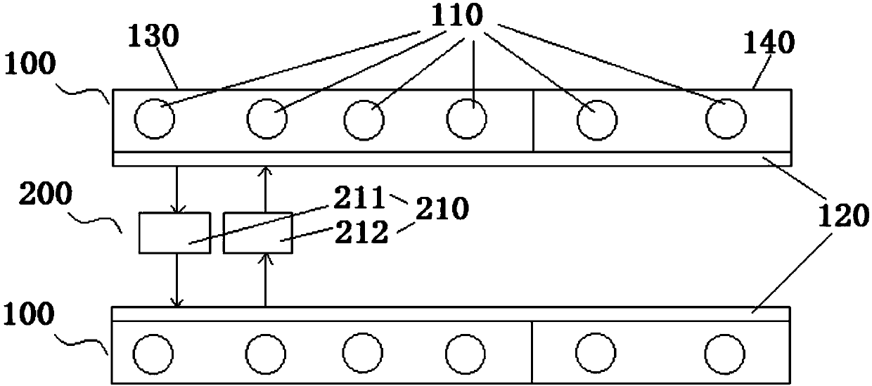
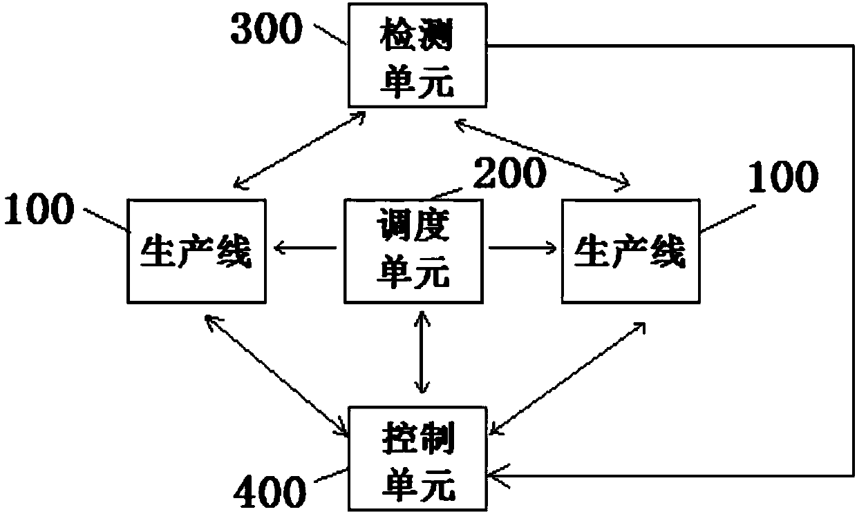
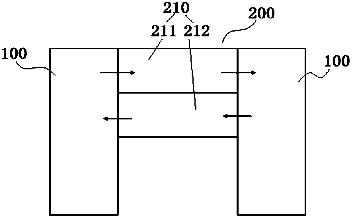
The invention relates to a photoetching system and a photoetching method thereof. The system comprises: at least two production lines, each production line comprises a plurality of process units configured to perform photoetching of a wafer; a detection unit configured to detect the working states of the process unit in the production lines; a control unit connected with the detection unit and configured to receive signals of the working states sent by the detection unit and generate control signals according to the working states of the process units in the production lines; and a dispatchingunit configured to transmit the wafer from the production line to the other adjacent production line according to the control signals of the control unit. The method comprises the steps of: receivingthe working states of the process units in the production lines from the detection unit; determining whether the working states of the process units in the production lines generate faults or not; and when the working states of the process units in the production lines generate faults, generating first control signals by the control unit to allow the dispatching unit to transmit the wafer from the production line to the other adjacent production line. The photoetching system is flexible in work and can meet the batch production of wafers.

Description


Claims


Application Information

Patent Timeline
Owner CHANGXIN MEMORY TECH INC
Why Eureka
Try Eureka