Testing device for fatigue life of steel hole belt

A test device and fatigue life technology, applied in the field of mechanical engineering, can solve the problems that test equipment is difficult to apply to steel perforated belts, etc., and achieve the effects of easy inspection and maintenance, convenient disassembly, and simple structure

Inactive Publication Date: 2019-12-20
NORTHWEST A & F UNIV
View PDF0 Cites 1 Cited by
  • Summary
  • Abstract
  • Description
  • Claims
  • Application Information

AI Technical Summary

Problems solved by technology

However, due to the huge difference in structure and material between the steel perforated belt and the belt, i

Method used


Image

  • Testing device for fatigue life of steel hole belt
  • Testing device for fatigue life of steel hole belt

Examples


Embodiment Construction

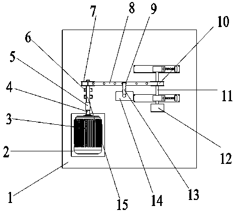
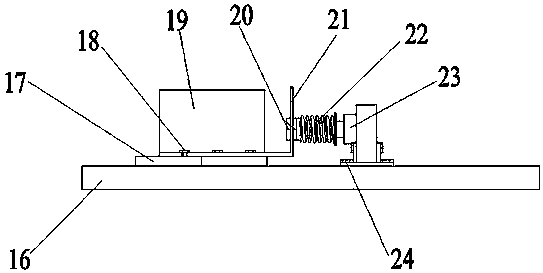
[0019] Specific embodiments are given below in conjunction with the drawings. An embodiment of the present invention is to test the fatigue life of the steel hole belt under set load conditions. As shown in the figure, install the steel hole belt (8) on the driving wheel (7) and the driven wheel (10) , Turn the adjusting bolt (20), move the track slider (17) to drive the sliding bearing seat (19) to slide until the steel hole belt (8) is in tension, and tighten the adjusting bolt (20) to make the sliding bearing seat ( 19) Fix, turn on the magnetic powder brake (12), adjust the braking force to the set value, turn on the power of the counting sensor (13), and finally turn on the power of the motor (3) to rotate at the set speed, and then drive the steel The hole-making belt (8) rotates, and the counting sensor (13) starts counting until the steel hole-making belt (8) is broken, and the entire test work is completed.

[0020] The present invention can change the diameter of the driv


PUM


Abstract

The present invention relates to a device for performing fatigue testing on a steel hole belt, and belongs to the field of mechanical engineering. In order to test the fatigue life of the steel hole belt, the present invention discloses a testing device for a fatigue life of the steel hole belt. The technical scheme is that: a driving wheel end of the steel hole belt is driven by a motor to drivethe steel hole belt to rotate, a magnetic powder brake is used to adjust the load force on the steel belt, and a counting sensor is used to record the number of rotations of the steel belt from the beginning to the fatigue fracture. The testing device for the fatigue life of the steel hole belt has the following advantages that: (1) a position adjustment mechanism can be used to adjust a distancebetween two transmission wheels, and the steel hole belts of different lengths can be tested; (2) the magnetic powder brake can be used to adjust the load force on the steel hole belt, and steel holebelts with different fatigue strength can be effectively simulated for testing; and (3) the structure is simple, the disassembly is convenient, and inspection and maintenance are facilitated.

Description


Claims


Application Information

Patent Timeline
Owner NORTHWEST A & F UNIV
Why Eureka
Try Eureka