Transmission unit for preventing plasma gas deposition

A technology of plasma gas and transmission unit, which is applied in the direction of pipes/pipe joints/fittings, pipe heating/cooling, mechanical equipment, etc., which can solve the problems affecting the accuracy of plasma gas and the performance of the pipe body, so as to improve the heating effect and heating speed , improve the heating effect, easy to use

Pending Publication Date: 2019-12-27
无锡英普朗科技有限公司
View PDF0 Cites 0 Cited by
  • Summary
  • Abstract
  • Description
  • Claims
  • Application Information

AI Technical Summary

Problems solved by technology

When the plasma gas is transported, it is easy to deposit powder on the inner surface of the tube for transmission, which affects the accuracy of the plasma gas use and the performance of the tube.

Method used


Image

  • Transmission unit for preventing plasma gas deposition
  • Transmission unit for preventing plasma gas deposition

Examples


Example Embodiment

[0022] The following will clearly and completely describe the technical solutions in the embodiments of the present invention with reference to the accompanying drawings in the embodiments of the present invention. Obviously, the described embodiments are only some, not all, embodiments of the present invention. Based on the embodiments of the present invention, all other embodiments obtained by persons of ordinary skill in the art without making creative efforts belong to the protection scope of the present invention.

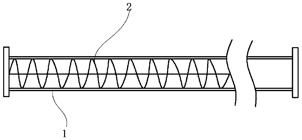
[0023] The invention discloses a transmission unit for preventing plasma gas deposition, comprising:

[0024] A tube body 1 with an inlet and an outlet, and a heating wire 2 arranged in the tube body 1;

[0025] The heating wire 2 extends from the inlet of the pipe body 1 to the outlet of the pipe body 1;

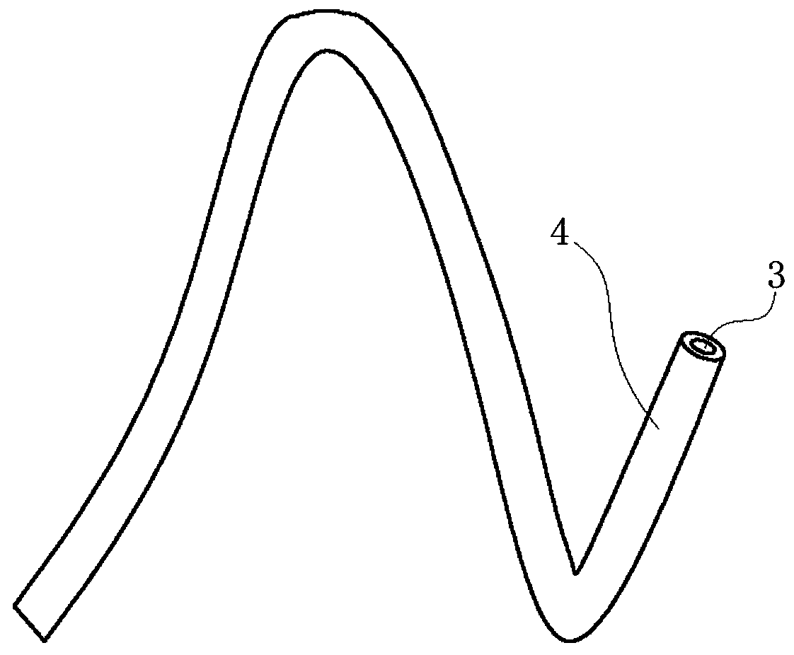
[0026] The heating wire 2 includes a first body and a second body sleeved outside the first body, the first body is a nickel-chromium alloy layer 3 , and the


PUM


Abstract

The invention relates to the technical field of gas transmission, and discloses a transmission unit for preventing plasma gas deposition. The transmission unit comprises a pipe body with an inlet andan outlet and a heating wire arranged in the pipe body, wherein the heating wire extends from the inlet of the pipe body to the outlet of the pipe body, the heating wire comprises a first body and a second body sleeves on the outer side of the first body, the first body is a nickel-chromium alloy layer, and the second body is a stainless steel layer. According to the transmission unit for preventing plasma gas deposition, the plasma gas can be continuously heated at each position in the pipe body, the heating speed of the plasma gas can be improved, and the plasma gas can be rapidly heated toa higher preset temperature.

Description


Claims


Application Information

Patent Timeline
Owner 无锡英普朗科技有限公司
Why Eureka
Try Eureka