Battery string welding mechanism

A welding mechanism and battery technology, applied in welding equipment, welding equipment, auxiliary welding equipment, etc., can solve the problems of high unqualified rate, waste of manpower, unfavorable product promotion, etc., and achieve high welding qualified rate, reasonable structural design, effective The effect of promotion

Inactive Publication Date: 2020-02-21
齐河双百数码影像设备有限公司
View PDF0 Cites 0 Cited by
  • Summary
  • Abstract
  • Description
  • Claims
  • Application Information

AI Technical Summary

Problems solved by technology

[0003] Most of the existing battery strings are welded manually, which wastes a lot of manpower and seriously affects the production efficiency; at the same time, its quality stability is poor and the failure rate is high, resulting in waste of product raw materials, which is not conducive to the promotion of products
[0004] Although there are some automatic welding equipments in the existing market, their welding stability is poor and the defect rate is high when they are actually used.

Method used


Image

  • Battery string welding mechanism
  • Battery string welding mechanism
  • Battery string welding mechanism

Examples


Example Embodiment

[0029] The technical solutions in the embodiments of the present invention will be clearly and completely described below in conjunction with the drawings in the embodiments of the present invention.

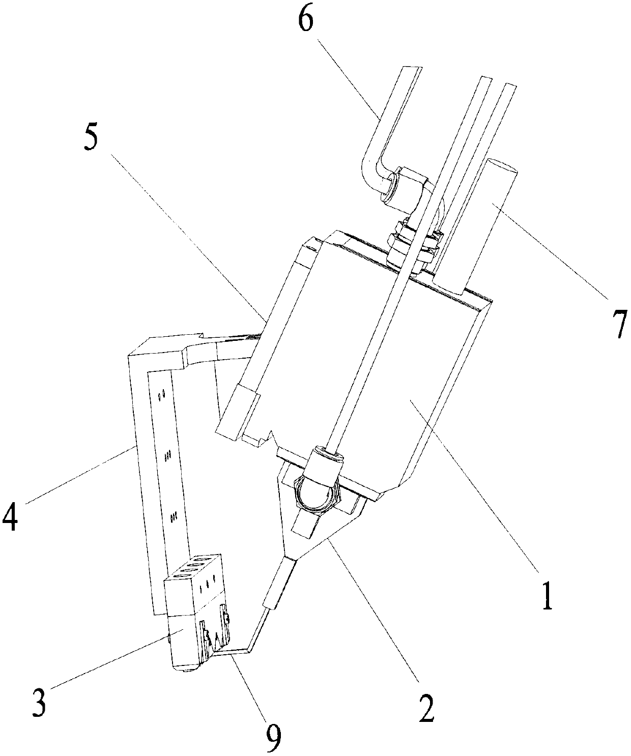
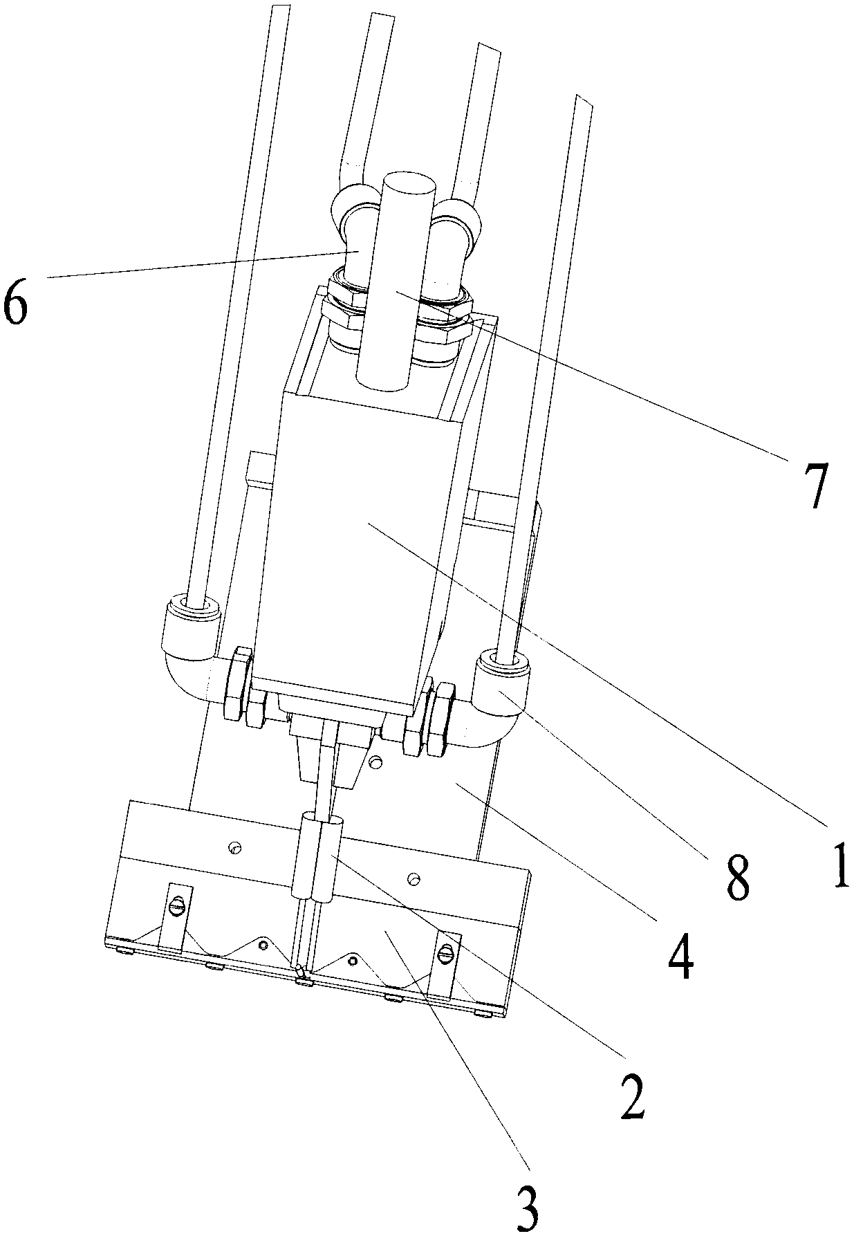
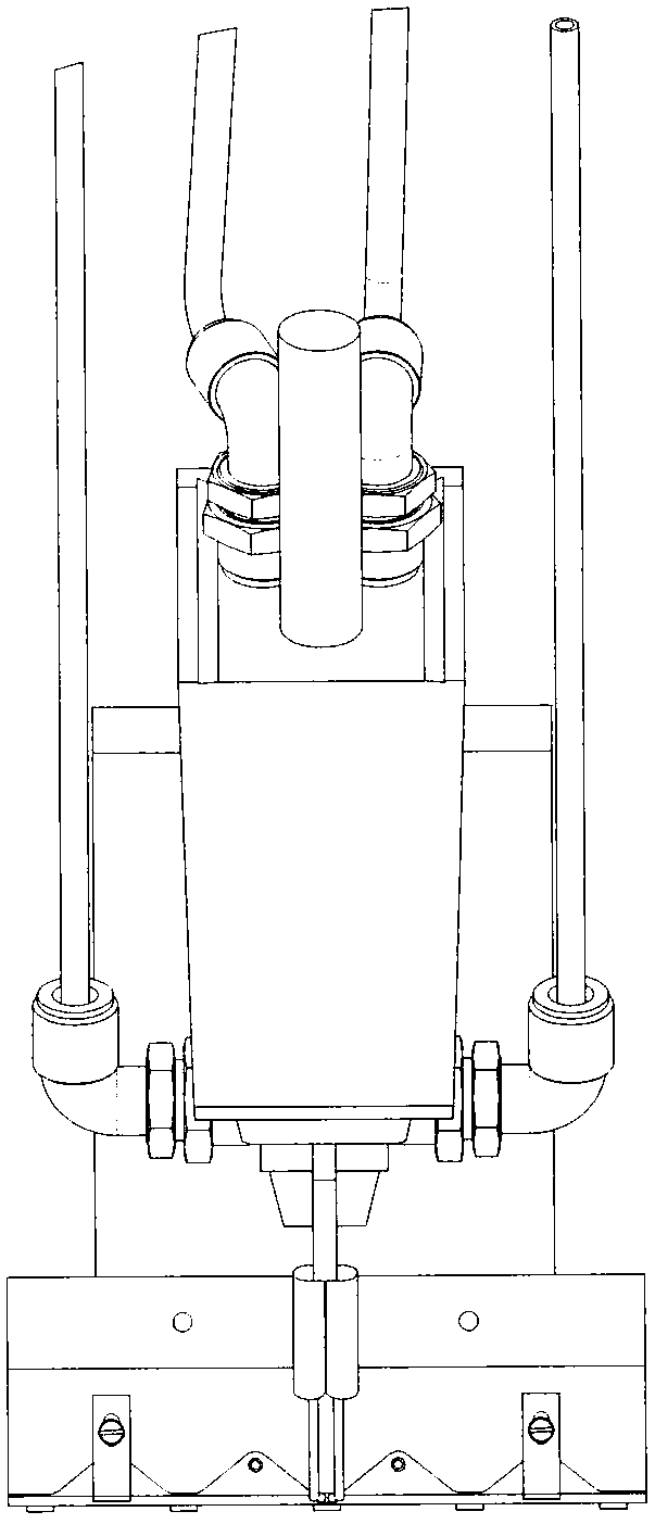
[0030] The specific structure is as Figure 1-3 As shown, the battery string welding mechanism includes an induction head 1, an induction rod 2, a welding head 3, a lifting frame 4, an induction head fixing seat 5, a circulating water pipe joint 6, and a power cord 7. The lower end of the induction head 1 passes The upper end of the induction rod 2 is screwed, and the lower end of the induction rod 2 is connected to the wire 9 of the welding head 3. The upper end of the induction head 1 is hermetically connected to two circulating water pipe joints 6, and the two circulating water pipe joints 6 are used to connect the circulating water pipe. The head 1 provides circulating water to cool and control the temperature of the induction head 1 and the welding head 3 at the lower end; the ind


PUM


Abstract

The invention discloses a battery string welding mechanism which comprises an induction head, an induction rod and a welding head, wherein the lower end of the induction head is connected to the upperend of the induction rod; the lower end of the induction rod is connected to a hollow copper wire of the welding head; the upper end of the induction head is in sealed connection to two circulating water pipe joints; the two circulating water pipe joints are used for connecting circulating water pipes; circulating water is supplied to the induction head via the circulating water pipes; and the induction head also communicates with a power line, and a power source is provided for the induction head of the battery string welding mechanism via the power line. The battery string welding mechanismis applied to equipment for automatic confluence and welding of a battery string and has the beneficial effects that stability is high; a welding pass percent is high; waste is reduced; cost is reduced; and the mechanism is beneficial for product promotion.

Description


Claims


Application Information

Patent Timeline
Owner 齐河双百数码影像设备有限公司
Why Eureka
Try Eureka