Optical sample rod system for in-situ liquid and gas environment transmission electron microscope

An electron microscope, liquid gas technology, applied in circuits, discharge tubes, scientific instruments, etc., can solve problems such as functional limitations, inability to meet the requirements of research work, loss of original exploration ability and experience accumulation in scientific research, and avoidance. Corrosion, the effect of preventing safety hazards

Pending Publication Date: 2020-03-20
BEIJING UNIV OF TECH
View PDF5 Cites 0 Cited by
  • Summary
  • Abstract
  • Description
  • Claims
  • Application Information

AI Technical Summary

Problems solved by technology

The more serious problem is that the use functions of related products imported from my country are greatly restricted, and flexible demand customization makes it difficult to better meet the needs of my country's scientific research industry
Therefore, the in-situ sample rod system imported from abroad with a single external environment is far from meeting the requirements of research work in most cases, which greatly limits the development of my country's in-situ observation technology field.
More importantly, this bought-in technology development method has caused my country's scientific research to lose its ability to conduct original exploration and experience accumulation. This is a great challenge for the development of a new generation of original scienti

Method used


Image

  • Optical sample rod system for in-situ liquid and gas environment transmission electron microscope
  • Optical sample rod system for in-situ liquid and gas environment transmission electron microscope
  • Optical sample rod system for in-situ liquid and gas environment transmission electron microscope

Examples


Embodiment Construction

[0025] The specific implementation manner of the invention will be described in further detail below in conjunction with the accompanying drawings and embodiments. For the detailed description of these embodiments, it should be understood that those skilled in the art can practice the present invention, and can use other embodiments without departing from the spirit of the appended claims and the scope of the present invention. Modifications and / or changes are made to the examples shown. Furthermore, although specific features of the present invention are disclosed in the embodiments, such specific features can be properly modified to achieve the functions of the present invention.

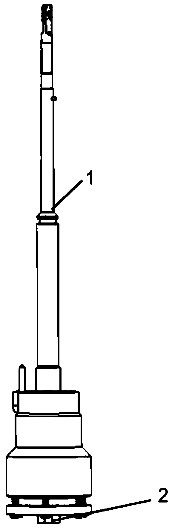
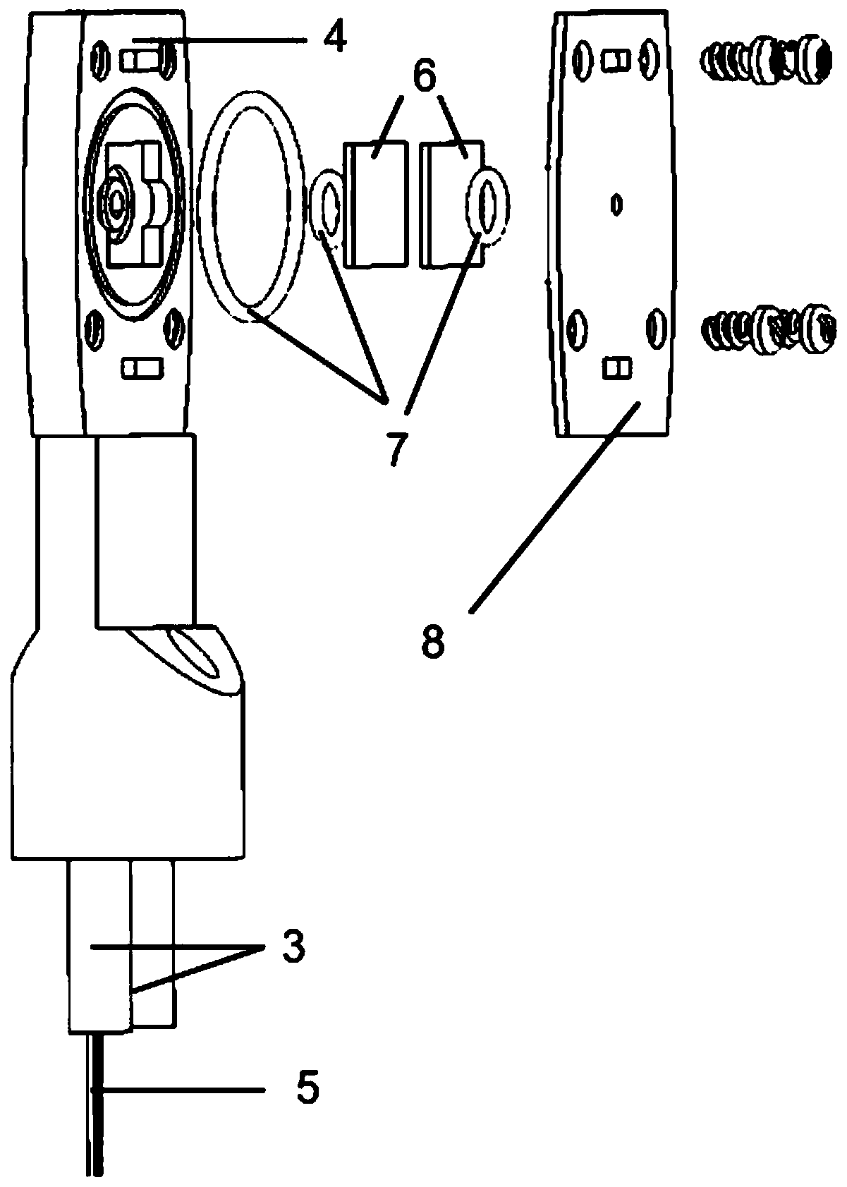
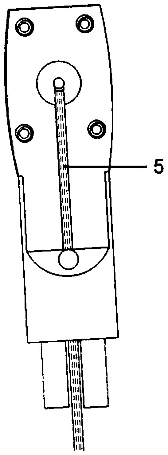
[0026] Such as Figure 1 to Figure 4 As shown, the optical sample rod system for in-situ liquid gas environment transmission electron microscope of the present invention includes: sample rod frame (1), high vacuum circular sealed connector (2), liquid gas dual-purpose conduit (3), small sample sta


PUM

PropertyMeasurementUnit
Wavelengthaaaaaaaaaa

Abstract

The invention discloses an optical sample rod system for an in-situ liquid and gas environment transmission electron microscope. The system comprises a sealed small sample table frame for manufacturing liquid and gas environments with different pressures in an ultrahigh vacuum environment, a hollow sample rod frame, a gas and liquid guide pipe arranged in the sample rod frame, an energy transmission optical fiber, a sealing rubber ring arranged in the small sample table frame and the like. A gas (liquid) environment exists in the sample rod head frame and is connected with external gas (liquid) inlet equipment through a gas (liquid) guide pipe. One end of the energy transmission optical fiber with the controllable wave band is fixed to the miniature sample table, and a main body of the energy transmission optical fiber extends out of a clamping groove in the miniature sample table, penetrates through the sample rod frame to be connected with an external light path unit and is used foradjusting the illumination environment in the miniature sample table. The system is suitable for exploring various physical and chemical life reaction processes such as gas-phase reaction, liquid-phase reaction, solid-phase and gas-phase interfaces, solid-phase and liquid-phase interfaces, photochemical reaction and the like.

Description


Claims


Application Information

Patent Timeline
Owner BEIJING UNIV OF TECH
Why Eureka
Try Eureka