Garbage compression dehydrator

A technology of garbage compression and dehydrator, which is applied in the direction of garbage drying, drying solid materials, and drying solid materials without heating. Good, easy to operate and maintain

Inactive Publication Date: 2020-03-27
保定市方正机械厂
View PDF8 Cites 2 Cited by
  • Summary
  • Abstract
  • Description
  • Claims
  • Application Information

AI Technical Summary

Problems solved by technology

[0003] The purpose of the present invention is to provide a garbage compression dehydrator to solve the problem of difficult collection and transportation of kitchen garbage

Method used


Image

  • Garbage compression dehydrator
  • Garbage compression dehydrator

Examples


Example Embodiment

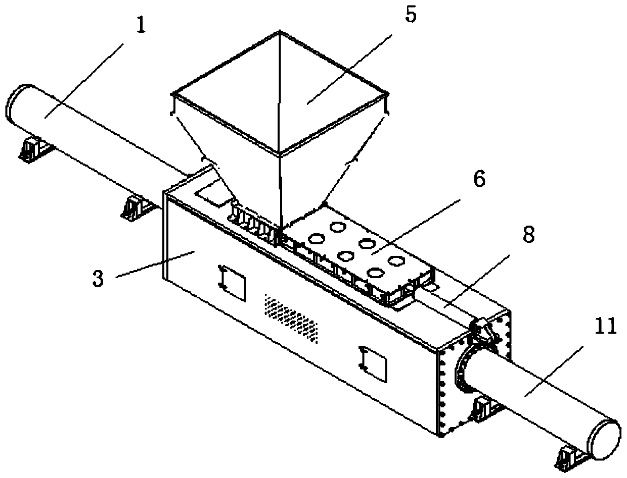
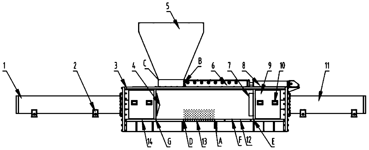
[0018] Such as figure 1 , 2 As shown, a garbage compression dehydrator includes a box body 3, and ribs are installed under the bottom plate of the box body 3 to play a role of strengthening and supporting. A sliding device 9 is slidably installed on the left and right sides of the inside of the box body 3. A number of rollers 10 are installed on the upper and lower, front and rear surfaces of the sliding device 9. In this embodiment, four are installed on the upper and lower ends. Two rollers 10 are installed on the front and rear surfaces of the roller 10 respectively. The inner side wall of the box body 3 is provided with a sliding groove matched with the roller 10 to ensure the smooth movement of the sliding device 9 so that the roller 10 does not jam during the movement.

[0019] The left end of the sliding device 9 on the left side is bolted to an oil cylinder 1 and a plug 4 is installed on the right end. The oil cylinder 1 passes through the left side wall of the box 3 and is


PUM


Abstract

The invention discloses a garbage compression dehydrator. The garbage compression dehydrator comprises a box body, wherein sliding devices are slidably arranged on the left side and the right side inside the box body; the left end of the left sliding device is connected with an oil cylinder I, the right end of the left sliding device is provided with an ejecting head I, and the oil cylinder I penetrates out of the left side wall of the box body to be electrically connected with a control device; an ejecting head II is arranged at the left end of the right sliding device, an oil cylinder III isconnected to the right end of the right sliding device, and the oil cylinder III penetrates out of the right side wall of the box body to be electrically connected with a control device; a slag discharging port, a water outlet hole and a discharging port are sequentially formed in the bottom end of the box body from left to right, a feeding port is formed in the upper end of the box body, and a hopper is arranged on the feeding port; and a hopper inserting plate is connected to the lower end of the hopper in an inserted mode, and the other end of the hopper inserting plate is connected with an oil cylinder II. According to the garbage compression dehydrator, a relay is adopted to control a circuit and control the oil cylinders to work, so that the automatic circulation process is realized, the structure is simple, the operation and maintenance are convenient, and the safety is high; the oil cylinders are adopted to provide squeezing force, the power is large, no conveying moving gap is achieved, the stability is good, and garbage is squeezed and dehydrated more fully and thoroughly.

Description


Claims


Application Information

Patent Timeline
Owner 保定市方正机械厂
Why Eureka
Try Eureka