Dislocation refueling device

A station and positioning seat technology, applied in the field of automation equipment, can solve problems such as low stability, reliability and safety, lower product competitiveness, and unfavorable production control, so as to facilitate production control, prevent product crushing, and save energy. The effect of manpower and time

Pending Publication Date: 2020-05-05
SUZHOU LINGYU ELECTRONICS TECH CO LTD
View PDF0 Cites 0 Cited by
  • Summary
  • Abstract
  • Description
  • Claims
  • Application Information

AI Technical Summary

Problems solved by technology

However, most of the existing nut pressing equipment manually places the plastic parts on the workbench of the equipment, and then positions and clamps the product through the corresponding positioning and clamping components. Every time the product is replaced, the equipment needs to be suspended, which is inconvenient to operate. It takes up a lot of manpower, takes a long time, a

Method used


Image

  • Dislocation refueling device
  • Dislocation refueling device
  • Dislocation refueling device

Examples


Embodiment

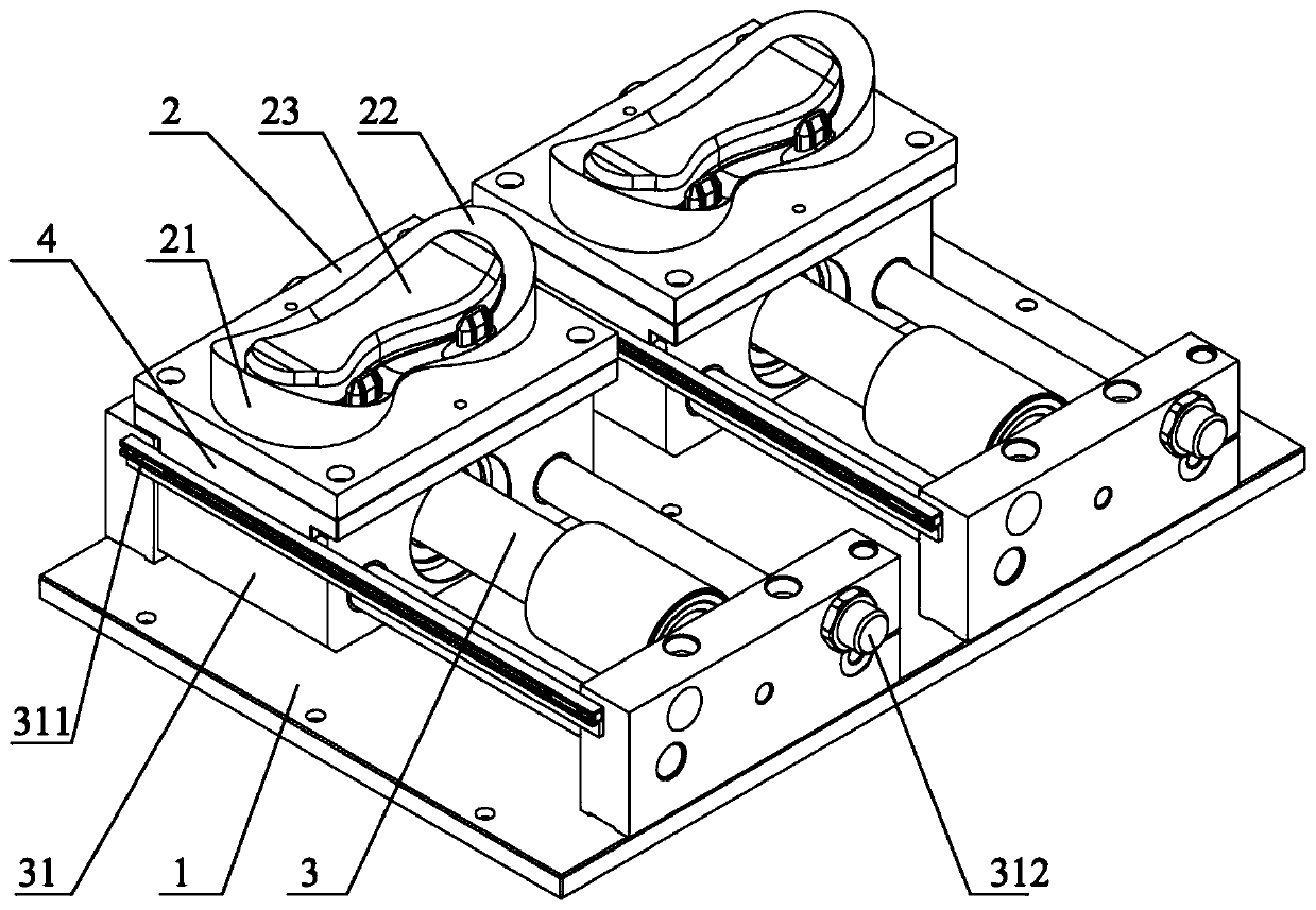
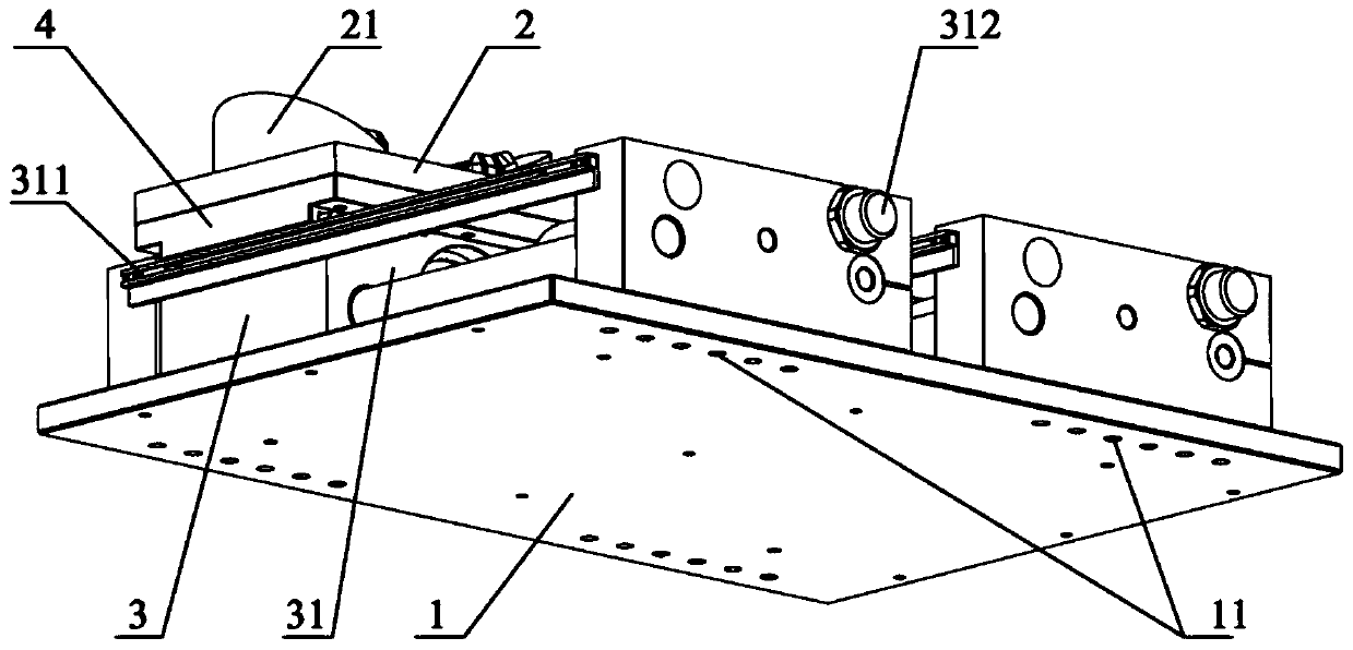
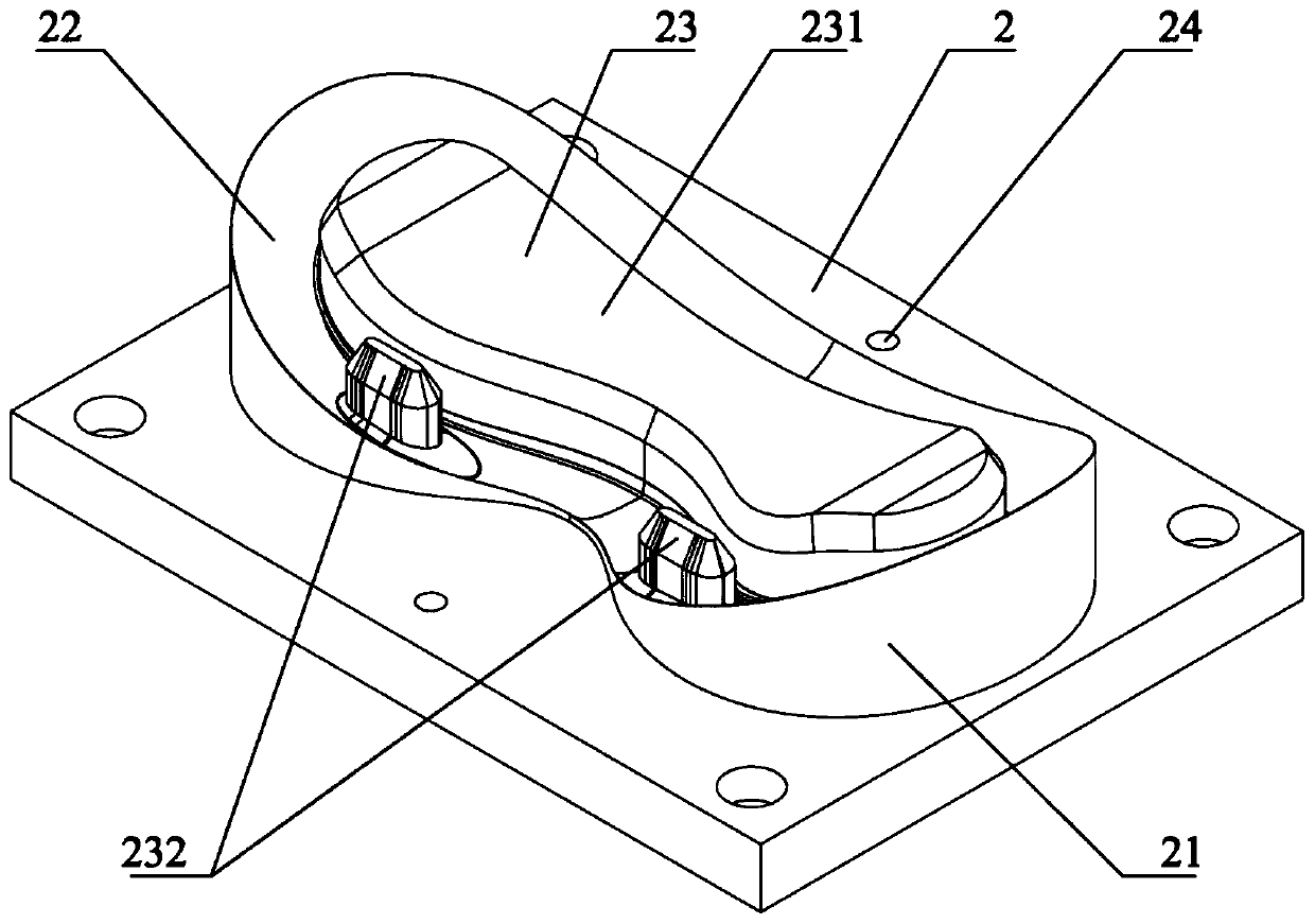
[0030] Such as Figure 1~5 As shown, a staggered refueling device is mainly used for compression nut equipment. The staggered refueling device includes a bottom plate 1. The bottom plate 1 is used to install at the corresponding position of the compression nut equipment. The bottom plate 1 is provided with two positioning seats 2 and Two linear motion mechanisms 3 that drive the two positioning bases 2 to reciprocate linearly, and the two linear motion mechanisms 3 are arranged side by side. The positioning base 2 is provided with a positioning table 21 for positioning and placing products, and the positioning table 21 is provided with The profiling groove 22 matched with the product is provided with a profiling table 23 for matching with the product. Usually the lower end of the product is placed in the profiling groove 22, and the profiling groove 22 can drag The product is positioned to support the product, and the cavity and hole of the product cooperate with the profiling tab


PUM


Abstract

The invention provides a dislocation refueling device which comprises a bottom plate. Two positioning seats and two linear motion mechanisms which respectively drive the two positioning seats to movelinearly and reciprocally are arranged on the bottom plate, the two linear motion mechanisms are arranged side by side, a positioning table used for positioning and placing products is arranged on thepositioning seas, a profiling groove used for being matched with the products is arranged on the positioning table, and a profiling table used for being matched with the products is arranged in the profiling groove. The two linear motion mechanisms can drive the two positioning seats to move in a dislocation mode so that one positioning seat is positioned at the processing station and the other positioning seat is positioned at a loading and unloading station. The dislocation refueling device has the advantages of simple structure, convenient operation, effective saving of manpower and time,improved production efficiency, accurate and stable product positioning, high product yield, no interference between product replacement and product processing, improved equipment stability, reliability and safety, convenient production management and control, and reduced production cost.

Description


Claims


Application Information

Patent Timeline
Owner SUZHOU LINGYU ELECTRONICS TECH CO LTD
Why Eureka
Try Eureka