Rotor of sand making machine and sand making machine

A sand making machine and rotor technology, applied in grain processing, etc., can solve the problems of high-efficiency crushing and low crushing efficiency of materials with different particle sizes, and achieve the effect of reducing kinetic energy difference and high crushing efficiency

Active Publication Date: 2020-06-23
CHINA RAILWAY CONSTR HEAVY IND
View PDF8 Cites 3 Cited by
  • Summary
  • Abstract
  • Description
  • Claims
  • Application Information

AI Technical Summary

Benefits of technology

This patented design allows for efficient rotation of an object made from two layers: one layer screens larger particles while another layer targets less ones like those bigger or lighter. By increasing this spacing between these layers, more finer objects are filtered away without being blocked up at certain parts during processing. Additionally, there's also good separation capabilities within each layer due to its positioned closer together near the center line compared to other areas where they shouldn’t be located further apart. Overall, this technology improves the quality of finished products produced through shaping processes such as casting moldings.

Problems solved by technology

This patented technology solves this issue where there may exist multiple chambers within the rotation mechanism of an already known type called the grinding wheel (grinder). These chambles store certain types of rocks while they break them up into smaller pieces before hitting another part like a roller table. By doing this effectively, the machines have more efficient use of space compared to traditional methods such as tampons or screens alone.

Method used


Image

  • Rotor of sand making machine and sand making machine
  • Rotor of sand making machine and sand making machine
  • Rotor of sand making machine and sand making machine

Examples


Embodiment Construction

[0027] The technical solutions in the embodiments of the present invention will be clearly and completely described below in conjunction with the accompanying drawings in the embodiments of the present invention. Obviously, the described embodiments are only a part of the embodiments of the present invention, rather than all the embodiments. Based on the embodiments of the present invention, all other embodiments obtained by those of ordinary skill in the art without creative work shall fall within the protection scope of the present invention.

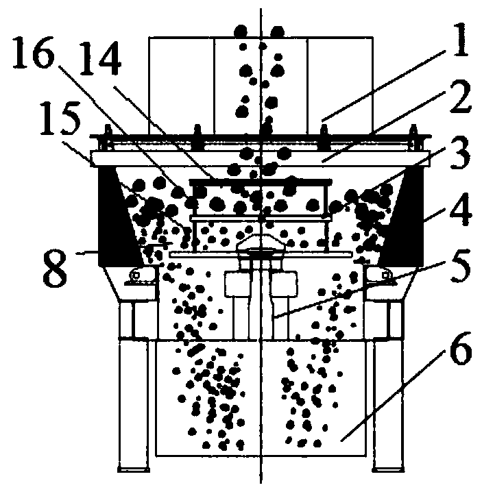
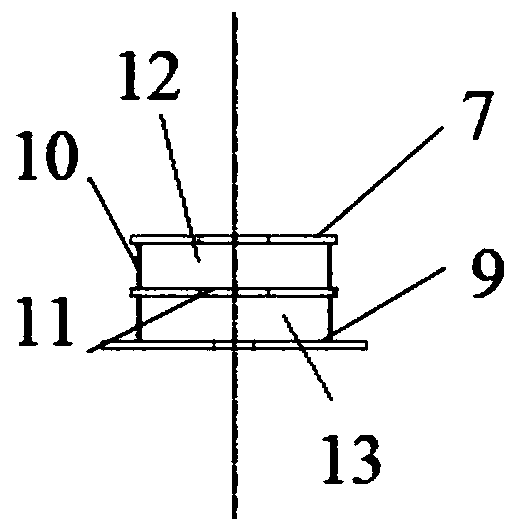
[0028] The core of the present invention is to provide a sand making machine rotor, which can improve material crushing efficiency. Another core of the present invention is to provide a sand making machine including the above-mentioned sand making machine rotor with high crushing efficiency.

[0029] It should be noted that when an element is referred to as "fixing" another element, it can be directly on the other element or a centered elemen


PUM


Abstract

The invention discloses a rotor of a sand making machine and the sand making machine. The rotor of the sand making machine comprises a rotor body. The rotor body comprises a rotor feed port, a screening plate and a lower face plate axially in sequence. Screening holes axially run through the screening plate. The distance between the edge of the lower face plate and the axis of the rotor body is larger than the distance between the edge of the screening plate and the axis of the rotor body. The portion, located between the rotor feed port and the screening plate, of the side face of the rotor body is provided with a first rotor discharge port. The edge of the first rotor discharge port and the edge of the screening plate are partly overlapped. The portion, between the screening plate and the lower face plate, of the side face of the rotor body is provided with a second rotor discharge port. The edge of the second rotor discharge port and the edge of the screening plate are partly overlapped. The rotor can screen materials of different grain sizes, and therefore different magnitudes of smashing energy can be adaptively provided for the materials of different grain sizes in the rotor,and the smashing efficiency of the sand making machine can be improved.

Description


Claims


Application Information

Patent Timeline
Owner CHINA RAILWAY CONSTR HEAVY IND
Why Eureka
Try Eureka