Power supply control device and electronic equipment

A technology for power supply control and electronic equipment, which is applied to circuit devices, measuring devices, and conversion equipment without intermediate conversion to AC, etc. It can solve the problems of complex control circuit design and cumbersome process, and achieve simple circuit, simple processing flow, and economical cost effect

Active Publication Date: 2020-07-10
XIAN WINGTECH INFORMATION TECH CO LTD
View PDF7 Cites 0 Cited by
  • Summary
  • Abstract
  • Description
  • Claims
  • Application Information

AI Technical Summary

Problems solved by technology

[0002] At present, the control circuit that supplies power to the embedded controller (Embeded Controller, EC) chip in electronic equipment is not only complicated in design
At the same time, whether it i

Method used


Image

  • Power supply control device and electronic equipment
  • Power supply control device and electronic equipment
  • Power supply control device and electronic equipment

Examples


Example Embodiment

[0032] The technical solutions in the embodiments of the present invention will be clearly and completely described below in conjunction with the accompanying drawings in the embodiments of the present invention. Obviously, the described embodiments are only a part of the embodiments of the present invention, rather than all the embodiments. The components of the embodiments of the present invention generally described and illustrated in the drawings herein may be arranged and designed in various different configurations.

[0033] Therefore, the following detailed description of the embodiments of the present invention provided in the accompanying drawings is not intended to limit the scope of the claimed invention, but merely represents selected embodiments of the present invention. Based on the embodiments of the present invention, all other embodiments obtained by those skilled in the art without creative work shall fall within the protection scope of the present invention.

[0034


PUM


Abstract

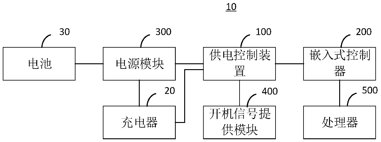
The embodiment of the invention provides a power supply control device and electronic equipment which are simple in circuit design and simple in processing flow. The power supply control device comprises an enabling control module and a voltage conversion module. The electronic equipment comprises an embedded controller, a power supply module and a startup signal providing module, the enabling control module is electrically connected with the voltage conversion module, the power supply module and the startup signal providing module, the voltage conversion module is electrically connected withthe embedded controller, the power supply module and the charger, and the power supply module is electrically connected with the battery or the charger; if the charger supplies power, the voltage conversion module receives a charging signal sent by the charger and converts a first working voltage provided by the power supply module into a second working voltage to supply power to the embedded controller according to the charging signal; if the battery supplies power, the voltage conversion module converts the first working voltage into the second working voltage to supply power to the embeddedcontroller according to an enable signal generated by the enable control module according to a startup signal sent by the startup signal providing module.

Description


Claims


Application Information

Patent Timeline
Owner XIAN WINGTECH INFORMATION TECH CO LTD
Why Eureka
Try Eureka