Rubber particle drying device

A technology of rubber granules and drying device, which is applied in the directions of drying gas arrangement, drying solid materials, drying chamber/container, etc., can solve the problems of increasing drying time, inability to adjust spacing, and inability to adjust, so as to improve drying efficiency and shorten drying time. , the effect of shortening the service life

Inactive Publication Date: 2020-08-11
郑家强
View PDF7 Cites 2 Cited by
  • Summary
  • Abstract
  • Description
  • Claims
  • Application Information

AI Technical Summary

Benefits of technology

This patented technology describes an improved rubber-particle drying machine called LCZ (Langely Coupled Zipper). It uses two separate devices - one acts like both a pump and valve system, allowing fluid pressure to flow freely without any resistance when moving parts together. Additionally, there are no springs inside these machines due to their design features such as compression/extension reversibility. These technical improvements help keep them working properly over longer periods compared to older designs.

Problems solved by technology

The technical problem addressed in this patented text relates to improving the efficient use of heat energy by optimizing the placement of rubble particles within an interior space where they can absorb water vapor from surrounding environment while also allowing them to freely move around without interferring or blocking their movement.

Method used


Image

  • Rubber particle drying device
  • Rubber particle drying device
  • Rubber particle drying device

Examples


Embodiment 1

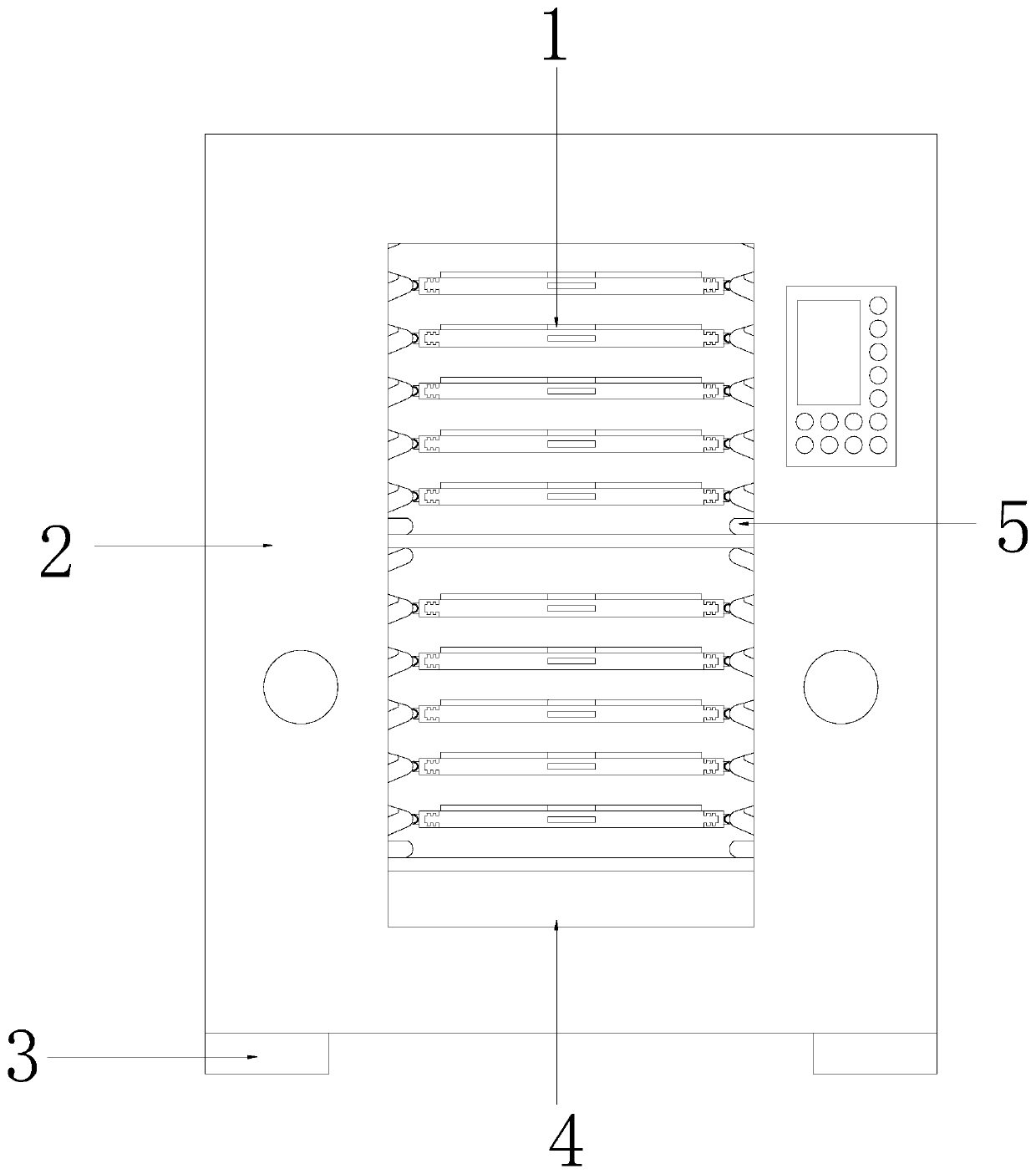
[0036] see Figure 1-7, the present invention provides a technical scheme of a rubber particle drying device: its structure includes a rubber particle drying rack 1, a drying body 2, a supporting foot 3, a rotary table 4, and a glass door 5, and the bottom of the drying body 2 is fixed with a supporting foot 3. The drying body 2 is equipped with a glass door 5, and the drying body 2 has a built-in rotary table 4, and the rotary table 4 is connected with a rubber particle drying rack 1, and the rubber particle drying rack 1 is also built in the drying body 2. The arrangement of the rotating table 4 enables the rubber granule drying rack 1 to rotate, which is beneficial to the uniform drying of the rubber granules and helps to improve the drying efficiency of the rubber granules.

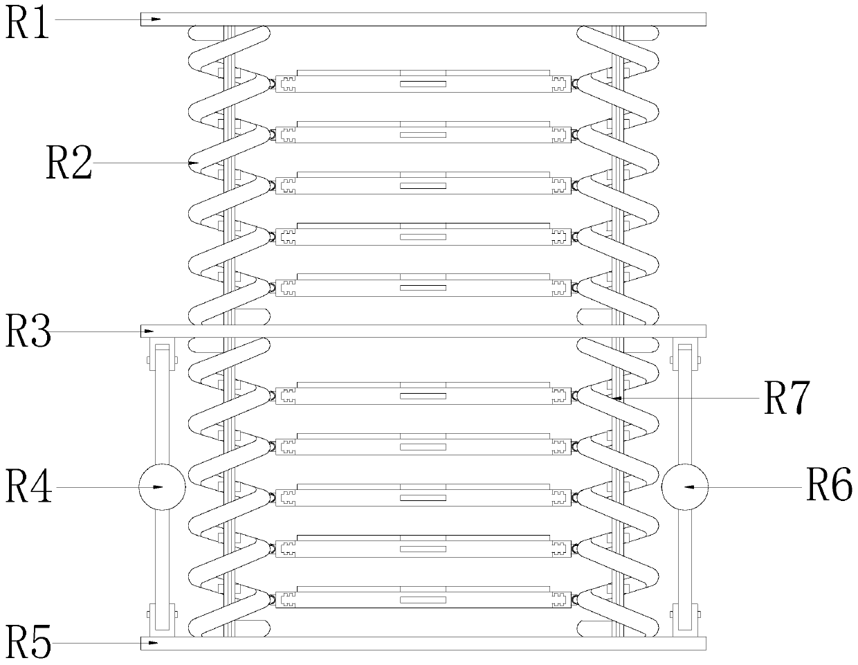
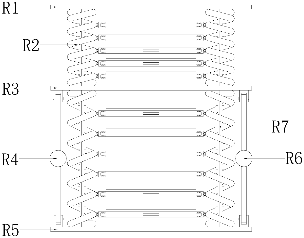
[0037] The rubber granule drying rack 1 includes a top plate R1, an upper rubber granule drying device R2, a partition plate R3, a No. 1 lifting device R4, a bottom plate R5, a No. 2 lifting device R6, a

Embodiment 2

[0041] see figure 1 , the present invention provides a technical scheme of a rubber particle drying device: its structure includes a rubber particle drying rack 1, a drying body 2, a supporting foot 3, a rotary table 4, and a glass door 5, and the bottom of the drying body 2 is fixed with a supporting foot 3. The drying body 2 is equipped with a glass door 5, and the drying body 2 has a built-in rotary table 4, and the rotary table 4 is connected with a rubber particle drying rack 1, and the rubber particle drying rack 1 is also built in the drying body 2. The arrangement of the rotating table 4 enables the rubber granule drying rack 1 to rotate, which is beneficial to the uniform drying of the rubber granules and helps to improve the drying efficiency of the rubber granules.

[0042] see Figure 2-5 , the rubber granule drying rack 1 includes a top plate R1, a drying device R2 on the rubber granules, a partition plate R3, a No. 1 lifting device R4, a bottom plate R5, a No. 2 l


PUM


Abstract

The invention discloses a rubber particle drying device. The rubber particle drying device structurally comprises a rubber particle drying frame, a drying machine body, supporting feet, a rotary tableand a glass door, wherein the supporting feet are fixed at the bottom of the drying machine body, the glass door is arranged outside the drying machine body, the rotary table is arranged inside the drying machine body, and the rubber particle drying frame is connected onto the rotary table. Compared with the prior art, the rubber particle drying device has the beneficial effects that due to the fact that springs are telescopic, the distance between spring rings can be increased or decreased at equal intervals when the springs are telescopic, the distance between drying nets can be changed along with the spring rings, the distance between the drying nets can be adjusted, rubber particles with different specifications can be adapted, the distance between the drying nets can be adjusted according to the amount of dried rubber particles, rapid circulation of hot air is facilitated, the hot air can better act on the rubber particles, the drying efficiency of the rubber particles is improved, the drying time is shortened, and the electric energy is saved.

Description


Claims


Application Information

Patent Timeline
Owner 郑家强
Why Eureka
Try Eureka