Air flue structure and humidifier

A humidifier and air duct technology, which is applied in the field of air duct structure and humidifiers, can solve the problems of back-injection into the air duct, affecting the normal use of the ultrasonic humidifier, and damage to the fan, and achieves the effect of reducing wind loss.

Pending Publication Date: 2020-09-11
GREE ELECTRIC APPLIANCES INC
View PDF0 Cites 0 Cited by
  • Summary
  • Abstract
  • Description
  • Claims
  • Application Information

AI Technical Summary

Benefits of technology

This patented device has two main technical features: one that prevents rainwater from getting inside the machine while it's being used by users who have intentionally wrongly spilled liquid onto their equipment (such as washing machines) during operation, causing harm if they are doing this with them. Another important characteristic involves prevention of condensation caused by excessive moisture ingress through certain parts of the system without affecting its performance.

Problems solved by technology

The technical problem addressed by this patented technology relates to improving the safety and efficiency of ultrasound humidifying devices used for indoor air conditioning systems due to potential damaging effects caused from rainwater entering the device's internal components during operation.

Method used


Image

  • Air flue structure and humidifier
  • Air flue structure and humidifier
  • Air flue structure and humidifier

Examples


Embodiment Construction

[0039] In order to make the above objects, features and advantages of the present invention more comprehensible, specific implementations of the present invention will be described in detail below in conjunction with the accompanying drawings. In the following description, numerous specific details are set forth in order to provide a thorough understanding of the present invention. However, the present invention can be implemented in many other ways different from those described here, and those skilled in the art can make similar improvements without departing from the connotation of the present invention, so the present invention is not limited by the specific embodiments disclosed below.

[0040] In describing the present invention, it should be understood that the terms "center", "longitudinal", "transverse", "length", "width", "thickness", "upper", "lower", "front", " Back", "Left", "Right", "Vertical", "Horizontal", "Top", "Bottom", "Inner", "Outer", "Clockwise", "Countercl


PUM


Abstract

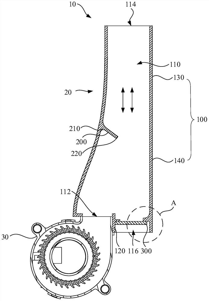
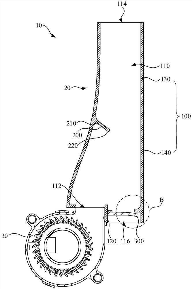
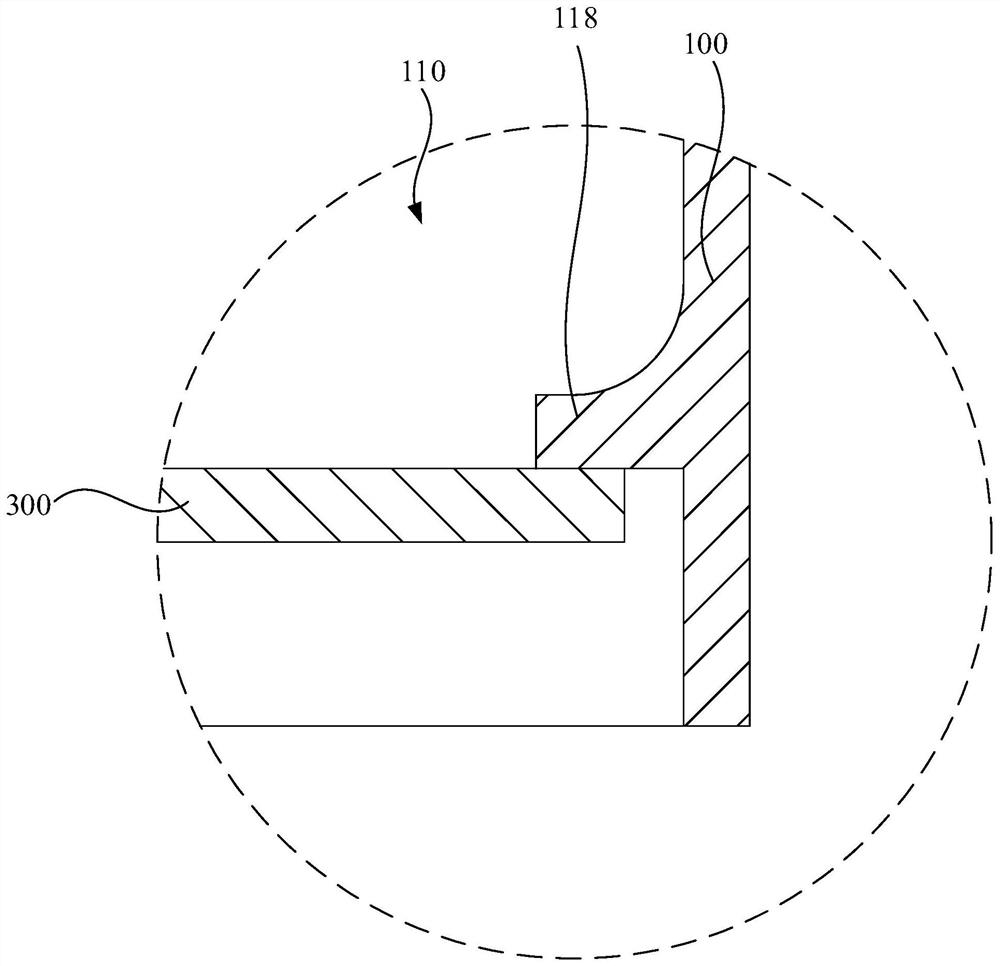
The invention discloses an air flue structure and a humidifier. The air flue structure comprises an air flue body, a shielding piece and an opening and closing piece; the air flue body is provided with an air flue; an air outlet, an air inlet and a water draining port are formed in the air flue; the shielding piece is arranged in the air flue; the shielding piece and the air inlet are arranged atan interval; the shielding piece is arranged to shield the air inlet; the opening and closing piece is connected to the air flue body and has a first working state and a second working state; when theopening and closing piece is at the first working state, the opening and closing piece is stressed to open the water draining port; and when the opening and closing piece is at the second working state and external force is removed, the opening and closing piece closes the water draining port. The air flue structure and the humidifier can prevent water from entering a draught fan during the usingprocess to further protect the draught fan from damage.

Description


Claims


Application Information

Patent Timeline
Owner GREE ELECTRIC APPLIANCES INC
Why Eureka
Try Eureka