Light guide plate making method, light guide plate and side-entering backlight module
A manufacturing method and technology of light guide plates, applied in the field of light guides, can solve the problems of long production cycle and complex manufacturing process of light guide plates, and achieve the effects of high assembly effect, saving design and production cycle, and high assembly efficiency
- Summary
- Abstract
- Description
- Claims
- Application Information
AI Technical Summary
Benefits of technology
Problems solved by technology
Method used
Image

Examples
Embodiment 1
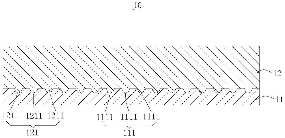
[0038] Please also refer to figure 1 and figure 2 , the manufacturing method of the light guide plate provided by the present invention will now be described. The manufacturing method of the light guide plate is used to manufacture the light guide plate 10 with functions of light guiding, uniform light and reflection.
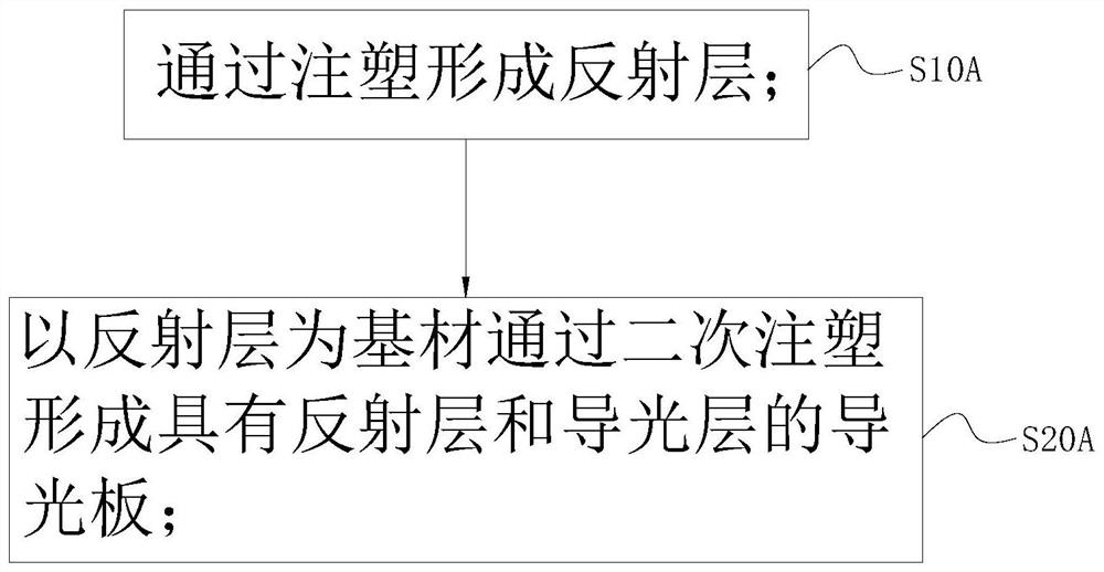
[0039] The manufacturing method of the light guide plate includes the following steps:
[0040] S10A: forming a reflective layer 11 by injection molding, and the reflective layer 11 has a reflective effect;
[0041] Specifically, it refers to injecting the melted first raw material into a thin plate-shaped reflective layer 11 through operations such as pressurization, injection, cooling, and detachment, wherein the first raw material is any plastic material with reflective function.
[0042] S20A: using the reflective layer 11 as the base material to form the light guide plate 10 with the reflective layer 11 and the light guide layer 12 through secondary injec
Embodiment 2
[0058] The difference between the manufacturing method of the light guide plate in this embodiment and the manufacturing method of the light guide plate in the first embodiment is as follows: please refer to Figure 5 , in this embodiment, the light guide layer 12 is formed first, and then the reflective layer 11 is formed. The specific steps are as follows:
[0059] S10B: forming a light guiding layer 12 by injection molding, the light guiding layer 12 has a light guiding effect;
[0060] Specifically, it means that the melted second raw material is injected to form the light guide layer 12 in a thin plate shape through operations such as pressurization, injection, cooling, and detachment, wherein the second raw material is any plastic material with light guiding function.
[0061] S20B: Forming the light guide plate 10 with the reflective layer 11 and the light guide layer 12 by secondary injection molding with the light guide layer 12 as the base material, and the reflective l
Embodiment 3
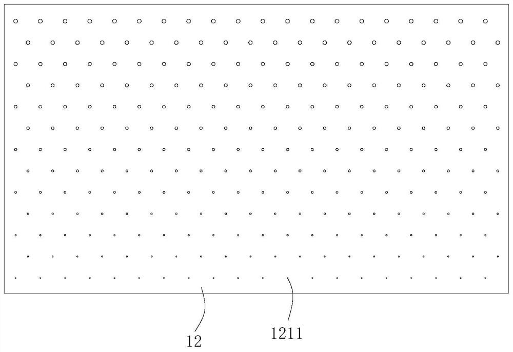
[0067] The manufacturing method of the light guide plate in this embodiment is the same as the manufacturing method of the light guide plate in the first embodiment, the difference is: please refer to Figure 6 , in this embodiment, the first optical part 111 includes a plurality of second convex points 1112, the second optical part 121 includes a plurality of second concave points 1212, and each second concave point 1212 is connected to each second convex point 1112 one by one. Corresponding cooperation. Wherein, the second concave point 1212 and the second convex point 1112 are only to be distinguished from the first concave point 1111 and the first convex point 1211 in name, and their structure is the same, and the distribution mode of the second concave point 1212 is the same as that of the first The distribution of the pits 1111 is the same.
[0068] Correspondingly, in order to form each second convex point 1112 during the first injection molding, the third optical part co
PUM
| Property | Measurement | Unit |
|---|---|---|
| Thickness | aaaaa | aaaaa |
| Thickness | aaaaa | aaaaa |
| Thickness | aaaaa | aaaaa |
Abstract
Description
Claims
Application Information
 - R&D Engineer
- R&D Manager
- IP Professional
- Industry Leading Data Capabilities
- Powerful AI technology
- Patent DNA Extraction
Browse by: Latest US Patents, China's latest patents, Technical Efficacy Thesaurus, Application Domain, Technology Topic.
© 2024 PatSnap. All rights reserved.Legal|Privacy policy|Modern Slavery Act Transparency Statement|Sitemap