Automatic pipe string processing equipment

A technology for processing equipment and pipe strings, applied in drilling equipment, drill pipes, casings, etc., can solve the problems of low degree of automation, high labor intensity, safety risks, etc., and achieve high degree of automation, low labor intensity, and no risk. Effect

Pending Publication Date: 2020-10-13
SANY GRP
View PDF0 Cites 5 Cited by
  • Summary
  • Abstract
  • Description
  • Claims
  • Application Information

AI Technical Summary

Problems solved by technology

[0003] The purpose of this application is to provide an automatic pipe string processing equipment, which solves to a certain extent the technical problems ex

Method used


Image

  • Automatic pipe string processing equipment
  • Automatic pipe string processing equipment
  • Automatic pipe string processing equipment

Examples


Embodiment Construction

[0039] The technical solutions of the present application will be clearly and completely described below in conjunction with the accompanying drawings. Apparently, the described embodiments are some of the embodiments of the present application, not all of them.

[0040] The components of the embodiments of the application generally described and shown in the figures herein may be arranged and designed in a variety of different configurations. Accordingly, the following detailed description of the embodiments of the application provided in the accompanying drawings is not intended to limit the scope of the claimed application, but merely represents selected embodiments of the application.

[0041] Based on the embodiments in this application, all other embodiments obtained by persons of ordinary skill in the art without making creative efforts belong to the scope of protection of this application.

[0042] In the description of this application, it should be noted that the terms


PUM


Abstract

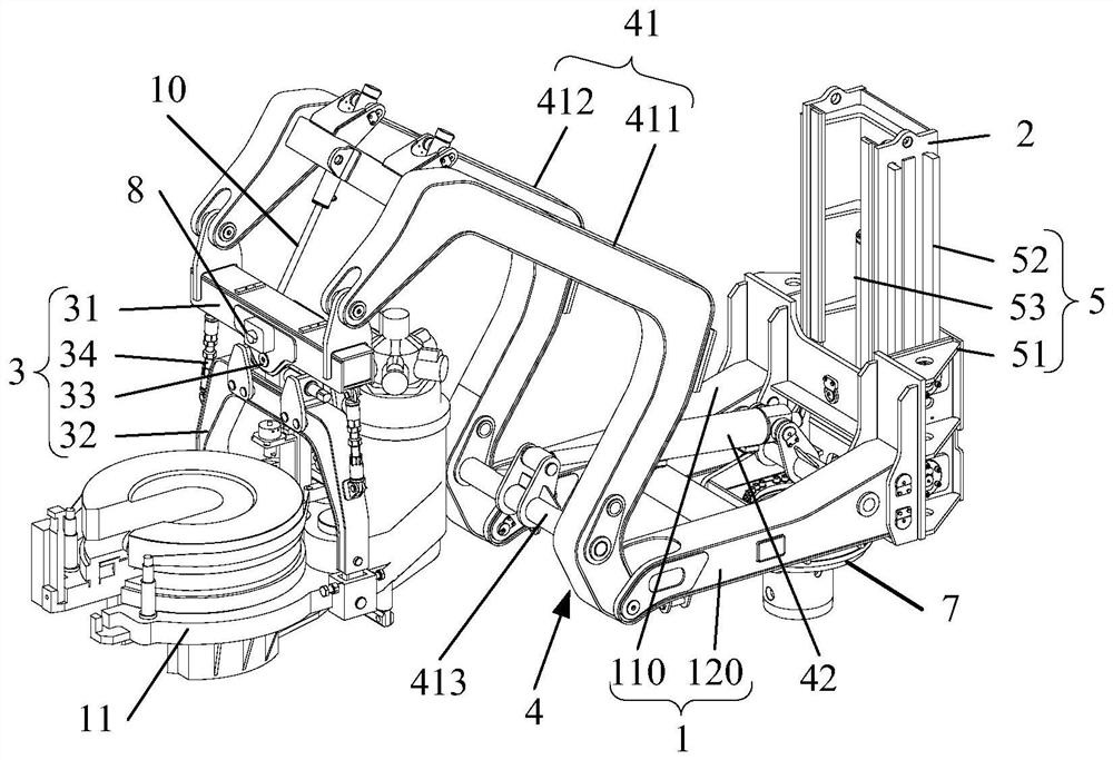
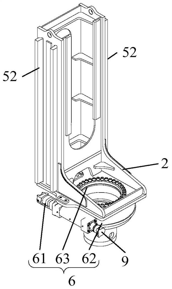
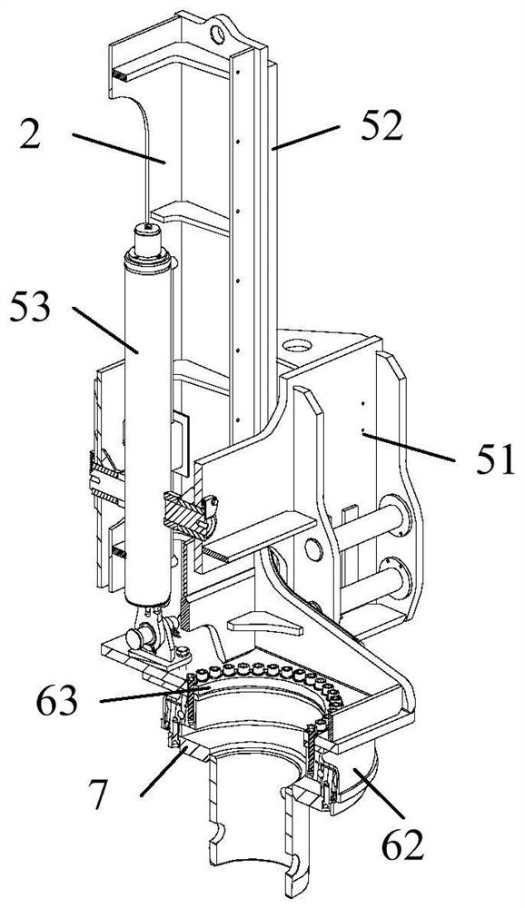
The invention relates to the technical field of iron roughneck, in particular to automatic pipe string processing equipment which includes a first supporting member, a second supporting member, a toolinstallation mechanism, a turning mechanism, a lifting mechanism, and a rotating mechanism. The tool installation mechanism is connected to the first supporting member through the turning mechanism,and the turning mechanism is used to drive the tool installation mechanism to turn over relative to the first supporting member; the first supporting member is connected to the second supporting member through the lifting mechanism, and the lifting mechanism is used to drive the first supporting member to lift and lower relative to the second supporting member; and the second supporting member isconnected to a target to be installed through the rotating mechanism, and the rotating mechanism is used to drive the second supporting member to rotate relative to the target to be installed. Therefore, the device can realize the adjustment of the turning, lifting, lowering and rotation of the tool installation mechanism, and the tool installation mechanism can move from a standby position to a wellhead, the automation degree is high, the labor intensity is low, no risk exists, and the automatic pipe string processing equipment is safer and more reliable.

Description


Claims


Application Information

Patent Timeline
Owner SANY GRP
Why Eureka
Try Eureka