Method of hardening tool edge through soldering wire and tool edge fixture

A knife edge and knife technology, applied in the field of knife edge hardening treatment method and the jig used to realize the above method, can solve the problems of increasing the price of the knife, the requirement of management environment, and the expensive cost of cladding powder, etc.

Pending Publication Date: 2020-10-27
BMAN MFG ZHE JIANG
View PDF1 Cites 0 Cited by
  • Summary
  • Abstract
  • Description
  • Claims
  • Application Information

AI Technical Summary

Problems solved by technology

[0002] Traditional tool materials generally choose stainless steel, and in order to ensure the final performance of the tool, after the tool body is formed by stamping, its strength, hardness and wear resistance are improved through heat treatment technology; however, ordinary martensitic stainless steel is used instead of The hardness of the finished cutting tool can only reach about 600HV after heat treatment and strengthening, and this hardness value can no longer meet people's requirements for high hardness and high wear resistance that high-end cutting tools should have.
[0003] At present, the way many domestic enterprises solve the above problems is to directly select foreign high-quality steel as the tool material, such as using Japanese laminated steel to manufacture high-performance knives, so as to ensure the performance of the final knives, especially the hardness of the blade. However, this will greatly increase the purchase cost of the tool material, resulting in an increase in the manufacturing cost of the tool, which in

Method used


Image

  • Method of hardening tool edge through soldering wire and tool edge fixture
  • Method of hardening tool edge through soldering wire and tool edge fixture
  • Method of hardening tool edge through soldering wire and tool edge fixture

Examples


Embodiment Construction

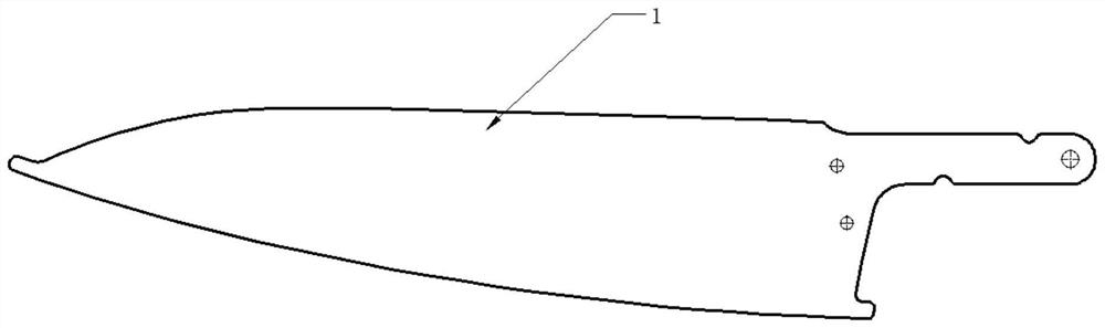
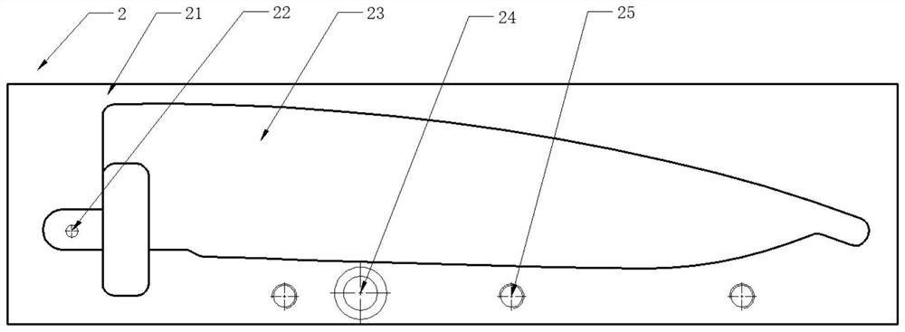
[0027] Combine below Figure 1-9 The present invention will be further described with specific embodiments.

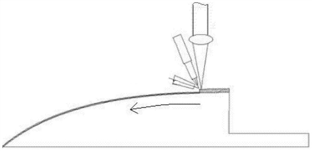
[0028] See attached figure 1 , which is a schematic diagram of the structure used in the powder edge hardening method in the prior art. It can be seen that in order to realize hardening treatment on both sides of the blade during the processing, the knife to be processed needs to be placed upright, that is, the tool processing process In all vertical machining, due to the arc structure of the tool blade, it is necessary to consider the transformation of the Z-axis height in the machining path programming, resulting in complicated machining; and because the machining method is point machining, it needs to be clad back and forth many times to achieve For the processing of a single knife, in order to ensure the processing quality, it is necessary to precisely control multiple working parameters such as laser power, laser focal length, powder output, shielding gas volume, m


PUM


Abstract

The invention discloses a method of hardening a tool edge through a soldering wire and a tool edge fixture. The tool edge hardening treatment method comprises the steps of assembling a tool to be machined into a fixture base in the tool machining process to form an enclosed groove structure between the tool edge of the tool to be machined and the fixture base; and heating and melting the solderingwire into fluid, driving the fluid into the groove structure, and curing the fluid to complete one-time filling to form a hardening layer at the tool edge. According to the hardening treatment methodprovided by the invention, horizontal machining is adopted, and there is no need to consider to change the Z-axis height in path programming; after a blade is fixed to a die, turnover remachining isnot needed, and machining of the single tool can be completed just through one-time machining; and just by controlling operating parameters such as the current magnitude, the moving speed, the wire feed speed and the relatively less shielding gas amount, and the quality is controlled easily.

Description


Claims


Application Information

Patent Timeline
Owner BMAN MFG ZHE JIANG
Why Eureka
Try Eureka