Design method of near-junction cooling structure of ultrahigh heat flow radio frequency microsystem

A technology for cooling structures and design methods, applied in design optimization/simulation, constraint-based CAD, special data processing applications, etc. Reliability, optimal design results, and the effect of reducing design costs

Active Publication Date: 2020-10-27
XI AN JIAOTONG UNIV
View PDF4 Cites 1 Cited by
  • Summary
  • Abstract
  • Description
  • Claims
  • Application Information

AI Technical Summary

Benefits of technology

This technology uses an algorithm calledStoke's Flow Model (SFM) that predicts how well different parts of a system will perform when they work together under specific conditions or environments during operation. By calculating these properties accurately without relying solely upon any previous designs for optimal behavior, this approach allows for more efficient use of space while reducing cost-effective manufacturing processes.

Problems solved by technology

Technological Problem: Ultraviolet Microcavity (UVMC) devices are used at very high temperatures due to their ability to transmit signals over long distances without losing power or causing damage from excessive temperature fluctuations. To prevent this issue, UVM' s channels can be cooled with liquid crystal molecules that absorb infrared light instead of allowing it to pass freely across them. Additionally, there may also exist other methods like adding layers between different materials inside these tiny structures called laminates, but they require advanced techniques such as laser ablation or etched holes into certain material patterns.

Method used


Image

  • Design method of near-junction cooling structure of ultrahigh heat flow radio frequency microsystem
  • Design method of near-junction cooling structure of ultrahigh heat flow radio frequency microsystem
  • Design method of near-junction cooling structure of ultrahigh heat flow radio frequency microsystem

Examples


Embodiment Construction

[0051] The present invention will be further described in detail below in conjunction with the accompanying drawings and embodiments.

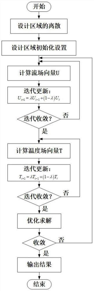
[0052] refer to figure 1 , a method for designing a near-junction cooling structure of an ultra-high heat flow radio frequency microsystem, comprising the following steps:

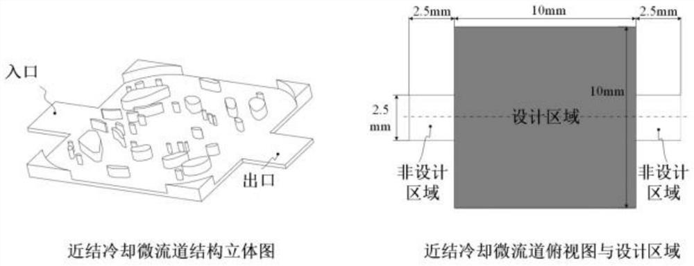
[0053] 1) Discretization of the design area: such as figure 2 As shown, the near-junction cooling micro-channel is symmetrical up and down along the horizontal center line, the size of the middle channel area is 10(mm)×10(mm), and the left and right sides of the channel area are 2.5(mm)× 2.5 (mm) entrance and exit area, the design area only includes the middle flow channel area; the design area is discretized into 120×240 finite element elements, and the discretized design area includes 120 rows and 240 columns;

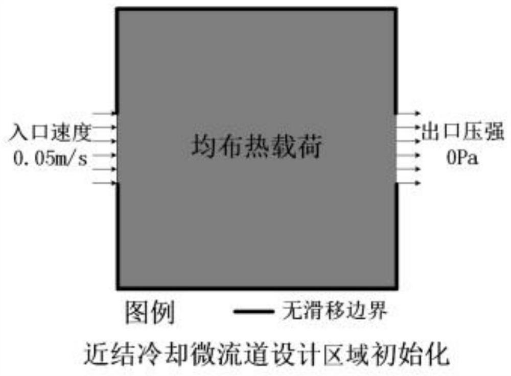
[0054] 2) Design area initialization settings:

[0055] 2.1) The use of the Stokes flow model: set the fluid flow state in the design area as laminar flow, and


PUM


Abstract

The invention discloses a design method of a near-junction cooling structure of an ultrahigh heat flow radio frequency microsystem. Firstly, carrying out discretization of a design area; setting boundary conditions according to actual working conditions; introducing reverse permeability and thermal conductivity related to the pseudo-density value to initialize a finite element model of a design area; carrying out finite element analysis according to a Stokes flow model and a convective diffusion equation; obtaining information of a flow field and a temperature field in an iterative computationmode; calculating a target function by utilizing the obtained physical field information; iterating under MMA algorithm updating according to the constraint function, the target function and the sensitivity of the constraint function to the design variable until the maximum fluid volume ratio allowed in the design process and the maximum outlet and inlet pressure difference allowed in the designprocess are met at the same time, or the number of iterations reaches the set maximum number of iterations. According to the method, the design reliability is improved, the design efficiency is higher, the design result is better, and meanwhile the design cost is reduced.

Description


Claims


Application Information

Patent Timeline
Owner XI AN JIAOTONG UNIV
Why Eureka
Try Eureka