Amorphous alloy transformer with circular iron core and short-circuit-resistant structure, and manufacturing method thereof

A technology of amorphous alloy and manufacturing method, applied in the direction of inductor/transformer/magnet manufacturing, transformer/inductor core, transformer/inductor components, etc., can solve the impact of production efficiency and production cost, and weak resistance to short-circuit force , increase manufacturing costs and other issues, to achieve the effect of improving production efficiency, reducing production time, and reducing material weight

Pending Publication Date: 2020-11-27
TBEA SHENYANG TRANSFORMER GRP CO LTD +1
View PDF0 Cites 0 Cited by
  • Summary
  • Abstract
  • Description
  • Claims
  • Application Information

AI Technical Summary

Benefits of technology

This patented technology allows for faster and easier creation of round electrical conductors by making them stronger while also being lighterweight compared to traditional methods like pressing or bending metal wire around shapes that require expensive tools during fabrication. Additionally, this new method avoids certain steps involved when producing these types of materials due to their unique shape.

Problems solved by technology

The technical problem addressed in this patents relates to improving the performance and durability of amorphously solidified (AS) alloys for use in electric generators that have low inductance but require less expensive raw materials than regular ones while still maintaining their excellent properties over longer periods without experiencing any damage from accidental short circuits caused by foreign objects or environmental factors.

Method used


Image

  • Amorphous alloy transformer with circular iron core and short-circuit-resistant structure, and manufacturing method thereof
  • Amorphous alloy transformer with circular iron core and short-circuit-resistant structure, and manufacturing method thereof
  • Amorphous alloy transformer with circular iron core and short-circuit-resistant structure, and manufacturing method thereof

Examples


Embodiment Construction

[0059] The present invention will be further elaborated below in conjunction with the accompanying drawings of the description.

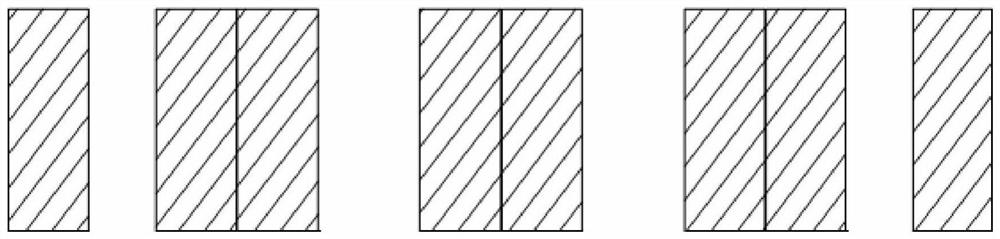
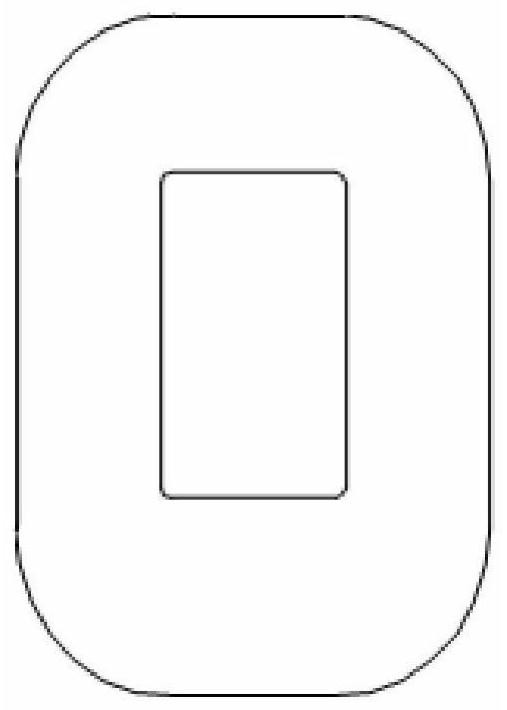
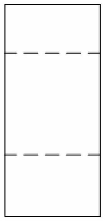
[0060] Such as Figure 5 , 6A As shown in ~6C, the present invention is an amorphous alloy transformer with a circular iron core anti-short circuit structure. The iron core adopts a three-phase five-column structure. Among the three main columns, each iron core column has four structures with the same structure and a cross-section of The circle formed by the combination of right-angle stepped single cores, and the side columns on both sides are semicircular formed by the combination of two right-angled stepped single cores with the same structure; the three main columns of the three-phase five-column structure are installed The coil forms the device body, and an upper clamping part and a lower clamping part are respectively installed on the body and the lower ends of the device.

[0061] Each right-angle stepped shape is made of rectangular amorphous


PUM


Abstract

The invention discloses an amorphous alloy transformer with a circular iron core and a short-circuit-resistant structure, and a manufacturing method thereof. Each iron core column is a circle formed by combining four single iron cores which are the same in structure and have right-angled stepped sections, and side columns on the two sides are semicircles formed by combining two right-angled stepped single iron cores which are the same in structure; and coils are mounted on the three main columns to form a transformer body. The method comprises the following steps: adopting a three-phase five-column structure; designing a manufacturing tool; optimally designing upper and lower clamping piece structures; assembling the main column iron core and the side column iron cores by using the manufacturing tool, opening the openings of the main column iron core and the side column iron cores, vertically placing the lower parts of the main column iron core and the side column iron cores on the manufacturing tool in a manner that the openings face upwards, and sleeving the coils into the iron cores from top to bottom after the iron cores are arranged; and after the iron core lamination is finished, installing the upper clamping piece and the lower clamping piece, and overturning the transformer body once to make the iron cores opened downwards and suspended on the coils. The production timeis shortened, a large amount of manufacturing cost is saved, the coil sudden short circuit passing rate is increased, and the state grid high-standard requirement is better met.

Description


Claims


Application Information

Patent Timeline
Owner TBEA SHENYANG TRANSFORMER GRP CO LTD
Why Eureka
Try Eureka