Cutter forging device of numerical control milling machine

A technology of CNC milling machine and console, applied in furnaces, heat treatment equipment, heat treatment furnaces, etc., can solve the problems of temperature reduction, inconsistent overall progress, inconsistent flame temperature to the highest point and range, etc., to achieve the effect of ensuring accuracy

Inactive Publication Date: 2020-12-04
北京俊南庆鑫物业管理有限公司
View PDF0 Cites 0 Cited by
  • Summary
  • Abstract
  • Description
  • Claims
  • Application Information

AI Technical Summary

Benefits of technology

This new design allows for better control over how much energy flows into an internal combustion engine's cylinders when they start up or stop running smoothly without any issues like excessive fuel consumption caused by insufficient coolant supply. It also ensures consistency from one part of the machine to another even if there may have different levels of activity at once (such as starting off). Overall this improves efficiency and performance while reducing environmental impact.

Problems solved by technology

The technical problem addressed in this patented text relates to improving cleanliness and hardiness during thermal processing (heat) treatment by optimizing the placement of an ignitor within the apparatus itself while ensuring consistency between different temperatures inside or outside the chamber.

Method used


Image

  • Cutter forging device of numerical control milling machine
  • Cutter forging device of numerical control milling machine
  • Cutter forging device of numerical control milling machine

Examples


Embodiment 1

[0027] as attached figure 1 to attach Figure 5 Shown:

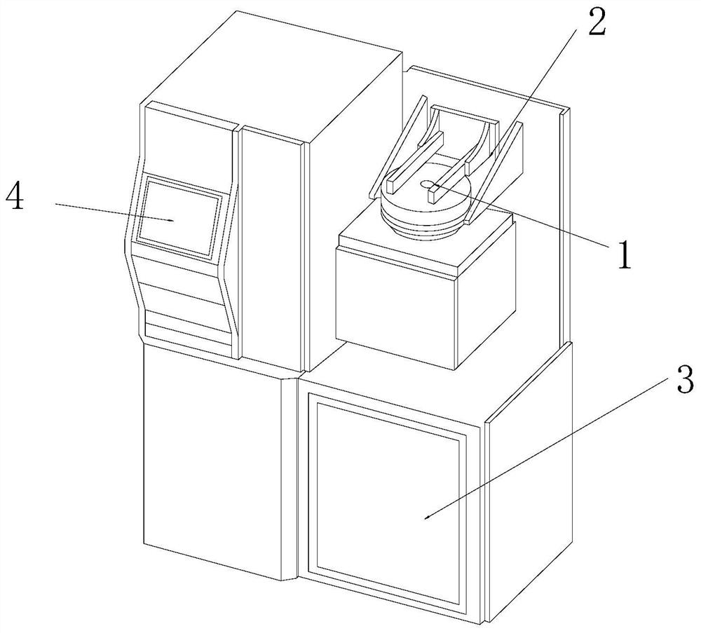
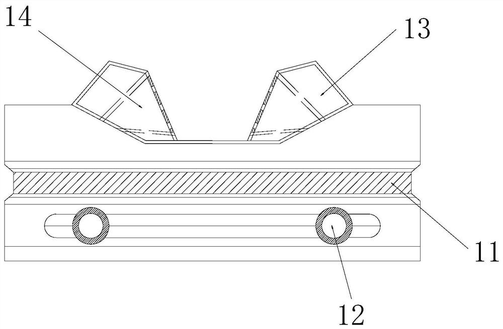
[0028] The present invention provides a knife punching device for a numerically controlled milling machine, the structure of which includes a fire plate 1, a clamper 2, a gas chamber 3, and a console 4. The fire plate 1 is inlaid directly below the clamper 2, The clamper 2 is located directly above the gas cabin 3, and the gas cabin 3 is embedded and installed under the right side of the console 4; The flame port 14, the adjustment mechanism 11 is inlaid directly above the heat dissipation port 12, the heat dissipation port 12 is symmetrically installed on the left and right sides of the lower end of the adjustment mechanism 11, and the fixed groove 13 is symmetrically embedded in the upper end of the fire tray 1 On the left and right sides, the flame port 14 is embedded in the inner end surface of the fixing groove 13 .

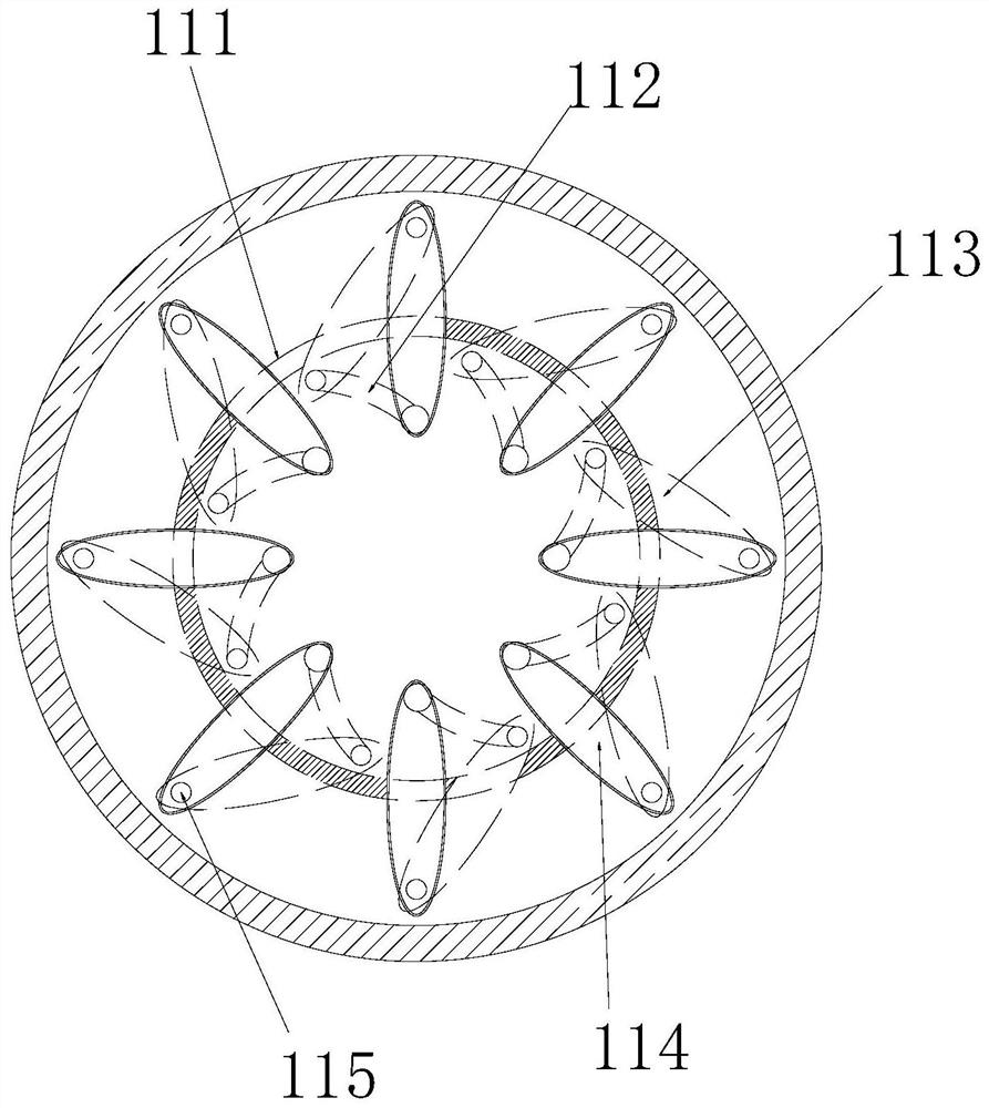
[0029] Wherein, the adjustment mechanism 11 includes a movable disk 111, a chute 112, an air-closin

Embodiment 2

[0034] as attached Figure 4 to attach Figure 8 As shown: the air-closing sheet 113 includes a connecting shaft 131, a folding layer 132, an air inlet 133, a sliding shaft 134, and a second flame outlet 135. The connecting shaft 131 is nested and connected to the movable shaft 115, and the folding layer 132 It is inlaid directly above the air inlet 133, the air inlet 133 is embedded and installed directly below the second flame outlet 135, the sliding shaft 134 is movably engaged with the inner end surface of the chute 112, and the second The flame outlet 135 is evenly inlaid on the inner surface of the upper end of the air-tight sheet 113. The folded layer 132 is made of multi-layer variable-direction interference plastic sheets, which can provide lateral movement capability when the air-tight sheet 113 swings, and ensure that the gas airtightness.

[0035]Wherein, the second flame outlet 135 includes an airtight ring 351, a cone-shaped valve 352, a second air inlet 353, and


PUM


Abstract

The invention discloses a cutter forging device of a numerical control milling machine. The cutter forging device of the numerical control milling machine structurally comprises a burning disc, a clamping device, a fuel gas cabin and a control table, wherein the burning disc is embedded under the clamping device; the clamping device is located overhead the fuel gas cabin; and the fuel gas cabin isfixedly embedded under the right side of the control table. In the working process, an adjusting mechanism can be rotated integrally, so that an air closing piece is driven to slide along an inner contour track of a sliding groove with a movable shaft as a center fulcrum; and a second flame outlet exposed in the air is changed along with the actual rotating progress through rotating adjustment, and effective and uniform heat treatment can be conducted on a workpiece to be machined, and the temperature inconsistency in the machining process due to layer-by-layer decreasing of the flame temperature caused by a fixed combustion area of a single flame opening is avoided.

Description


Claims


Application Information

Patent Timeline
Owner 北京俊南庆鑫物业管理有限公司
Why Eureka
Try Eureka