Elastic sheet production equipment with reverse folding machining function for electronic equipment

A technology for electronic equipment and production equipment, applied in the field of shrapnel production equipment, can solve problems such as failure to achieve production results, and achieve the effect of smooth operation

Inactive Publication Date: 2020-12-18
东莞市夯实科技有限公司
View PDF0 Cites 0 Cited by
  • Summary
  • Abstract
  • Description
  • Claims
  • Application Information

AI Technical Summary

Benefits of technology

This patented technology describes various technical features related to improving the manufacturing process of electronic devices such as lamps or cameras. These improvements include improved design techniques for guiding and controlling the movements of the components involved, increased flexibility in assembly processes, reduced risk of damage caused by excessive force applied overall, enhanced safety measures for handling these products safely within their designated areas without damaging them themselves.

Problems solved by technology

This patented technical problem addressed by this patents relates to improving the performance of thin metal materials (such as copper) during fabrication processes due to their low resistivity compared to traditional metals like iron). Additionally, there may exist situations where these materials require precise measurements over time without losing effectiveness caused by changes made through external forces. These issues make conventional methods difficult to implement effectively because they often involve repeated folds which lead to decreased durability and reduced accuracy.

Method used


Image

  • Elastic sheet production equipment with reverse folding machining function for electronic equipment
  • Elastic sheet production equipment with reverse folding machining function for electronic equipment
  • Elastic sheet production equipment with reverse folding machining function for electronic equipment

Examples


Embodiment Construction

[0028]The following will clearly and completely describe the technical solutions in the embodiments of the present invention with reference to the accompanying drawings in the embodiments of the present invention. Obviously, the described embodiments are only some, not all, embodiments of the present invention.

[0029] In the description of the present invention, unless otherwise stated, the meaning of "plurality" is two or more; the terms "upper", "lower", "left", "right", "inner", "outer" , "front end", "rear end", "head", "tail", etc. indicate the orientation or positional relationship based on the orientation or positional relationship shown in the drawings, and are only for the convenience of describing the present invention and simplifying the description, rather than Indicates or implies that the device or element referred to must have a particular orientation, be constructed and operate in a particular orientation, and therefore should not be construed as limiting the inv


PUM


Abstract

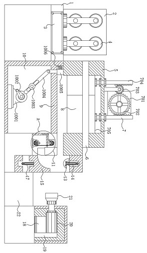
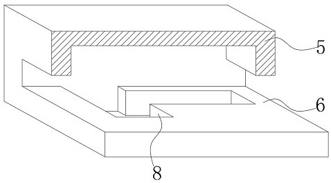
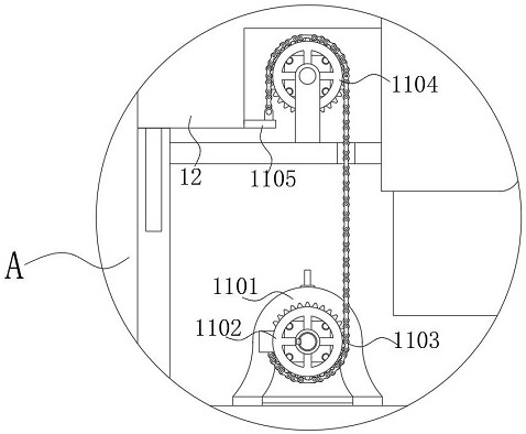
The invention discloses elastic sheet production equipment with a reverse folding machining function for electronic equipment. The elastic sheet production equipment comprises a bottom case, a first conveying mechanism is arranged on the upper surface of the left side of the bottom case, a punching hole is formed in the lower portion of an inner cavity of a punching case, a second stepping motor is arranged in an inner cavity of the right side of the bottom case, and sliding slopes are symmetrically arranged on the two sides of the portion, located below electric clamping plates, of the bottomcase. Bending blocks and guide blocks are arranged on the left side of an operation table, through arc arrangement of the bending blocks, arc bending of an elastic sheet is facilitated, when the guide blocks ascend to the arc bent curve of the elastic sheet, the elastic sheet is bent into an arc shape along the guide blocks, and bending plates are arranged on the two sides of the operation table,so that the two sides of the elastic sheet can be folded by 90 degrees conveniently, the defect that most devices can only bend the elastic sheet in a left-right staggered mode is overcome, and machining and forming of the elastic sheet are facilitated.

Description


Claims


Application Information

Patent Timeline
Owner 东莞市夯实科技有限公司
Why Eureka
Try Eureka