Ceiling shock absorber

A ceiling and shock absorber technology, applied in the direction of earthquake resistance, building components, building types, etc., can solve the problems of inconvenient installation and positioning of light steel keels, ceiling leveling, low bearing capacity of keel layers, and large space occupation, etc. The effect of installation positioning and ceiling leveling

Inactive Publication Date: 2021-03-19
广东邦达实业有限公司
View PDF10 Cites 0 Cited by
  • Summary
  • Abstract
  • Description
  • Claims
  • Application Information

AI Technical Summary

Benefits of technology

This new design allows an anchor rod or other device used during construction work to have different ways it's going around inside its body. It also makes it easy to install these devices at various angles without having them fixed permanently by bolts.

Problems solved by technology

This patented technical problem addressed by this patents relates to improving the performance of fiberglass reinforced cushion systems (FRCS) that use less material while maintaining their strength against bending loads or impact loadings during construction work.

Method used


Image

  • Ceiling shock absorber
  • Ceiling shock absorber
  • Ceiling shock absorber

Examples


Embodiment Construction

[0027] In order to enable those skilled in the art to better understand the technical solutions of the present invention, the present invention will be further described in detail below in conjunction with the accompanying drawings and specific embodiments. In describing the present invention, it should be understood that the terms "upper", "lower", "front", "rear", "left", "right", "top", "bottom", "inner", " The orientation or positional relationship indicated by "outside", etc. is based on the orientation or positional relationship shown in the drawings, and is only for the convenience of describing the present invention and simplifying the description, rather than indicating or implying that the referred device or element must have a specific orientation, so as to Specific orientation configurations and operations, therefore, are not to be construed as limitations on the invention.

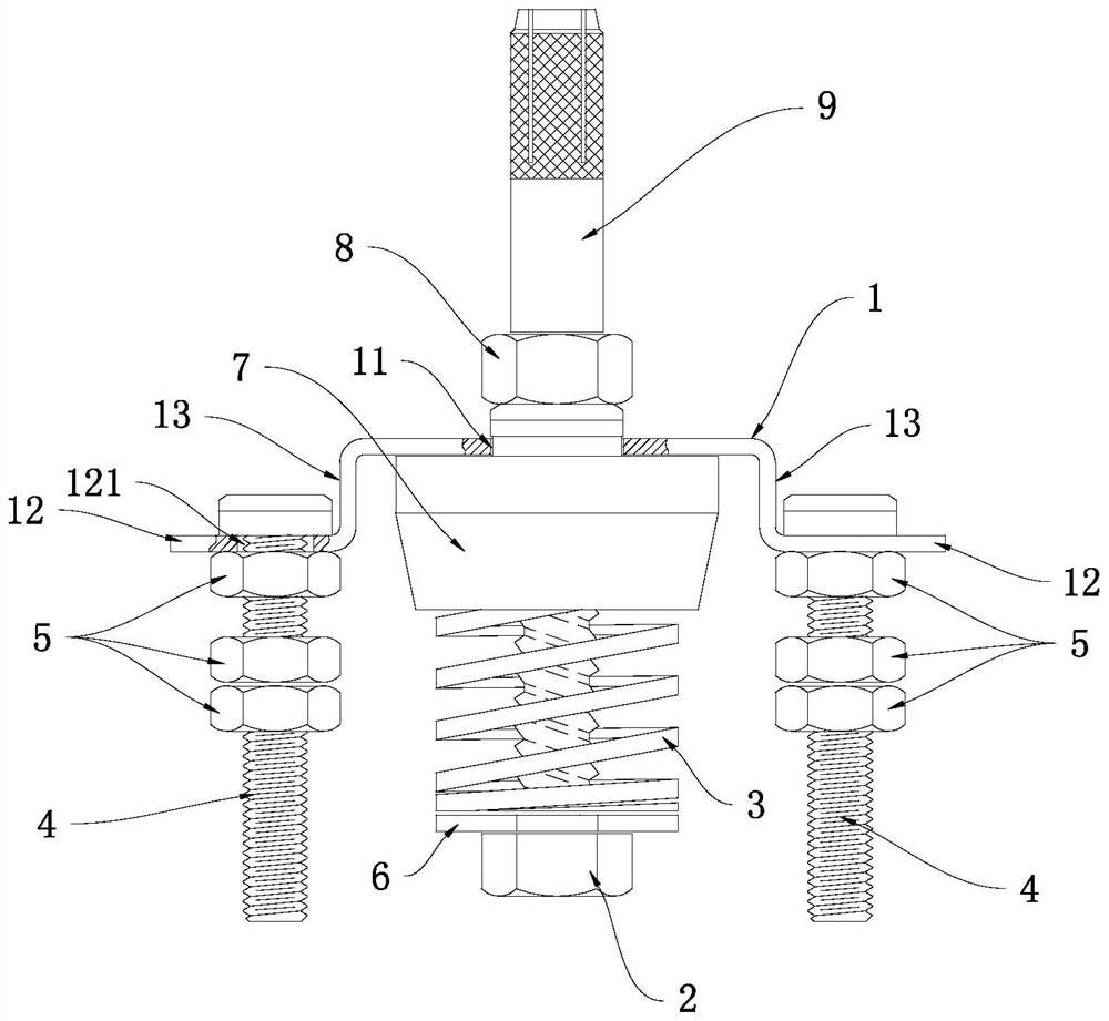
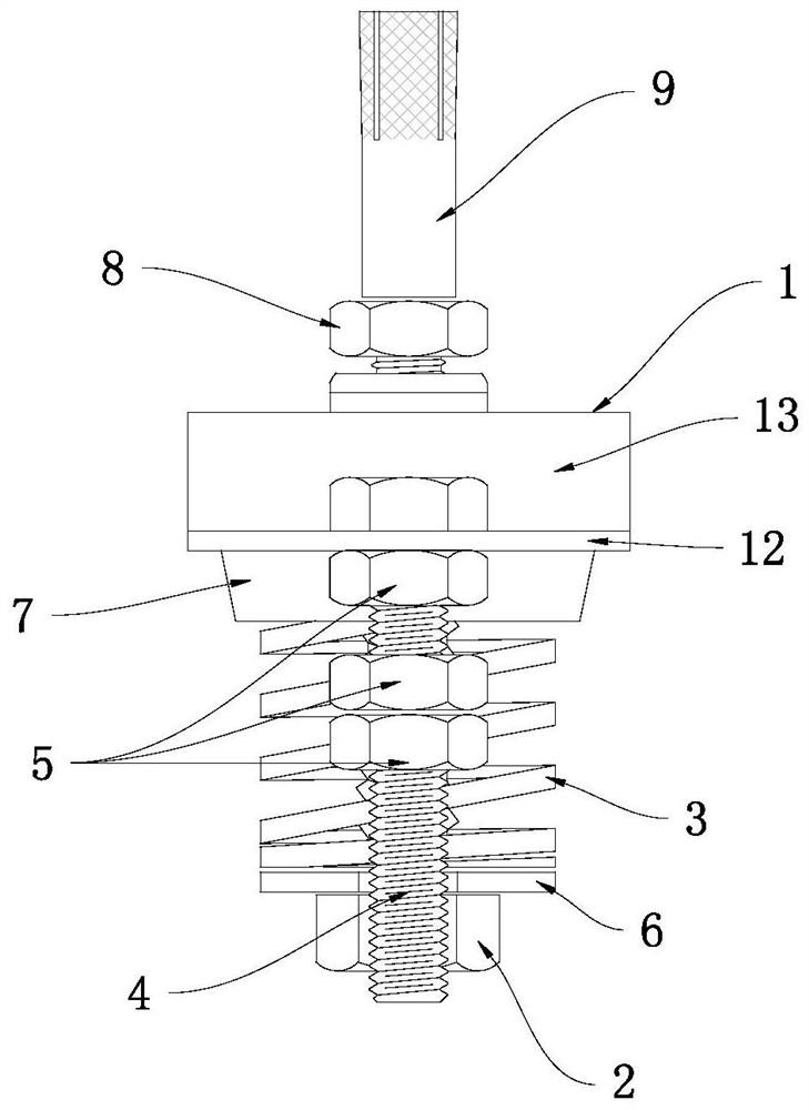
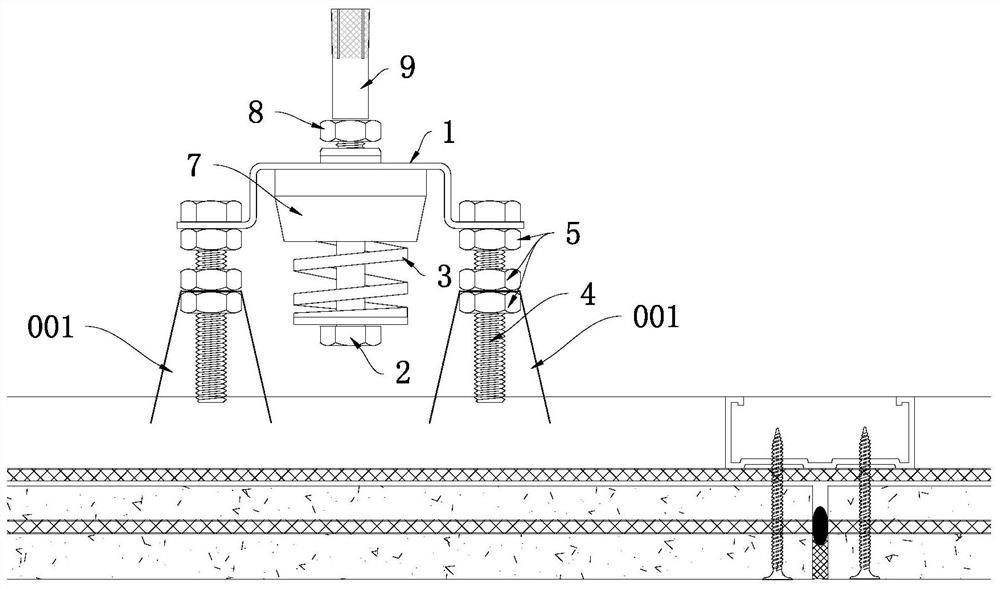
[0028] Such as Figure 1 to Figure 4 The shown ceiling shock absorber includes a frame 1 and


PUM


Abstract

The invention discloses a ceiling shock absorber. The ceiling shock absorber is simple in structure, easy to install, good in shock absorption effect, high in stability, small in occupied space in theheight direction and capable of facilitating ceiling element installation and positioning and ceiling leveling. The ceiling shock absorber comprises a frame (1) and a main bolt (2); a first through hole (11) allowing the main bolt (2) to penetrate through is formed in the middle of the frame (1); the rod portion of the main bolt (2) faces upwards and penetrates through the first through hole (11)from bottom to top; a fastening connecting part (9) used for being connected with a suspended ceiling is arranged on the upper portion of the rod portion of the main bolt (2); an elastic part (3) isarranged between the main bolt (2) and the frame (1) in a sleeved mode; and ceiling connecting parts used for being connected with ceiling elements (001) are arranged at the left side and the right side of the frame (1) respectively. The ceiling shock absorber is suitable for ceiling shock absorption.

Description


Claims


Application Information

Patent Timeline
Owner 广东邦达实业有限公司
Why Eureka
Try Eureka