Method for operating a bending machine

A technology for bending machines and operators, applied in the direction of press machines, computer control, general control systems, etc., can solve problems such as operating errors, unqualified, hindering workpiece application, etc.

Active Publication Date: 2021-04-02
TRUMPF MASCHEN AUSTRIA
View PDF26 Cites 0 Cited by
  • Summary
  • Abstract
  • Description
  • Claims
  • Application Information

AI Technical Summary

Benefits of technology

The present technology allows for precise control over how an object moves during manufacturing processes by providing symbolic representations that represent its movements with reference points on different axes within it's frame. This makes it easier for operators to interpret what they are doing when moving objects around inside them compared to traditional methods like linear motors.

Problems solved by technology

The technical problem addressed in these patents relates to improving efficiency during complicated processes involving high temperature heat treatments like hot roll bonding without causing any issues related to incorrect placement of parts within the process.

Method used


Image

  • Method for operating a bending machine
  • Method for operating a bending machine
  • Method for operating a bending machine

Examples


Embodiment Construction

[0028] As an introduction, it should be noted that in different described embodiments, the same parts have the same reference numerals or the same component names, wherein the disclosure contained in the entire specification can be referred to by reference to the same drawings. Mark or the same part of the same part name. Furthermore, selected position indications such as top, bottom, side, etc. in the description relate to the directly described and depicted figures, and in the event of a position change, these position indications shall be transferred mutatis mutandis to the new position.

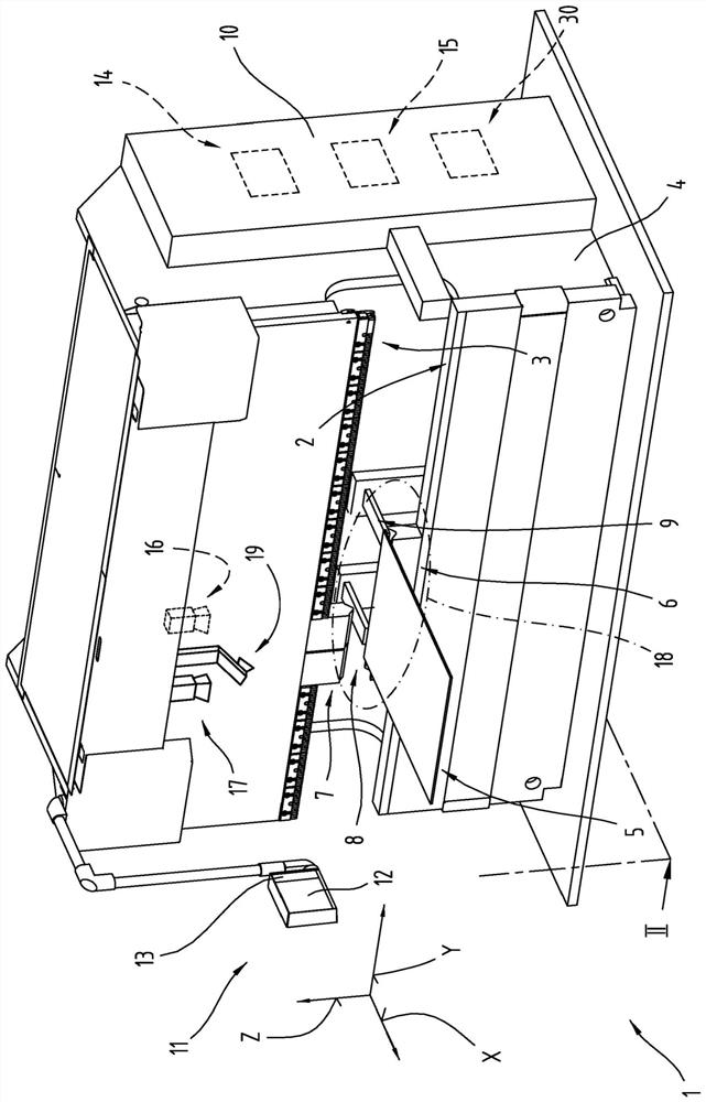
[0029] figure 1 A press brake 1 is shown as an example of a manufacturing plant or workpiece handling machine. The press brake 1 has a lower pressing beam 2 and an upper pressing beam 3 in a known manner. The two pressure beams 2, 3 are held by a frame 4 on which the lower pressure beam 2 is fixed (ie, stationary). The fixed hold-down beam 2 is therefore often also referred to as a table


PUM


Abstract

The invention relates to a method for producing a component by forming a workpiece (5) from sheet metal with a bending machine (1) comprising a control device (10) and a production program (14) for operating the bending machine (1), wherein at least two production steps, each involving forming by bending, are performed on the workpiece (5) in a working region (18), and wherein the working region (18) is monitored with a camera (16, 17) and images of the working region (18) are presented to the operator (20) by a display means (19), and wherein, during the performance of a first production step, the images of the working region (18) that are to be presented by the display means (19) are overlaid by an image processing program (15) with working instructions for a subsequent phase of the current, first production step or for a next-following, second production step, and are presented by the display means (19).

Description


Claims


Application Information

Patent Timeline
Owner TRUMPF MASCHEN AUSTRIA
Why Eureka
Try Eureka