Rapid cooling equipment for ceramic tiles

A ceramic tile, fast technology, applied in the field of ceramics, can solve problems such as easy cracks, ceramic appearance damage, ceramic strength reduction, etc., and achieve the effect of convenient cleaning

Active Publication Date: 2021-04-23
广州宏成科技信息有限公司
View PDF7 Cites 1 Cited by
  • Summary
  • Abstract
  • Description
  • Claims
  • Application Information

AI Technical Summary

Benefits of technology

This technology uses an apparatus called this device with two pipes: one goes towards the center where there are high-pressure gases from another source like compressed gas or liquid fuel; while the other sends it downstream along different directions. When the air flows into these tubings, its pressure increases but faster than before. These changes help remove any tiny particles found on the surface being coated without getting stuck inside them. By doing this, the resulting ceramics have improved purity compared to traditional methods such as water washing.

Problems solved by technology

The technical problem addressed in this patented text relates to how to quickly reduce the temperature when preparing ceramies for use at an outdoor location without causing any unwanted particles like sands on top of them being mixed up together This would lead to decreased durability and increased risk of failure if there were no effective way to prevent these contaminants getting inside the cerams themselves

Method used


Image

  • Rapid cooling equipment for ceramic tiles
  • Rapid cooling equipment for ceramic tiles
  • Rapid cooling equipment for ceramic tiles

Examples


Embodiment 1

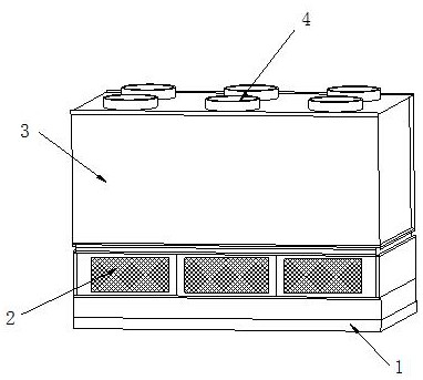
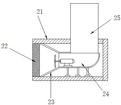
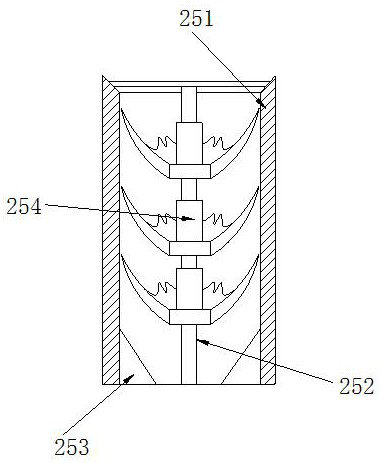
[0026]SeeFigure 1 - Figure 5 In particular, the present invention is specifically implemented, for example, a ceramic brick fast cooling device including a base 1, a winder 2, a cooling row 3, an exhaust pipe 4, the base 1 top surface and a winder 2 bottom welding, The top surface of the exhaust cartridge is embedded inside the cooling line 3, the venting tube 4 is turned on and the cooling line 3 is connected to each other and is connected by a welded; the exhaust fan 2 includes a housing 21, a filter cover 22, a centralized tube 23 The venting tube 24, the filter 25, the filter cover 22 is embedded on the left side of the outer casing 21, and the central tube 23 is welded to the outer casing 21, and the exhaust pipe 24 is left and centralized. 23 On the right side, the right side is connected to each other and the upper pipe 25 is embedded in the top surface of the outer casing 21, the upper surface of the upper pipe 25 and the exhaust pipe 24 to each other and by a welded connection

Embodiment 2

[0032]SeeFigure 6 - Figure 8The present invention is specifically implemented, for example, the contact handle A42 includes a mounting sleeve B1, a handle B2, a navigated head B3, a backgaged groove B4, a bonded head B5, and the mounting sleeve B1 outer layer is embedded in the bottom surface of the handle B2 The empty groove B3 is integrated with the inside of the handle B2, and the backgaged groove B4 is integrated with the right side of the handle B2, and the bonded head B5 is embedded in the inner layer of the reflow groove B4. The return groove B4 is provided with the bonded head B5, and the four return grooves B4 are uniformly distributed on the right side of the handle B2, which facilitates increasing the number of reflows and filters.

[0033]Wherein, the bonded head B5 includes a fixed block B51, a strond b 52, a rotary head B53, a contact plate B54, and the fixed block B51 bottom surface passes through the trust B52 and the rotary head B53 internal activity, the rotary head B53


PUM


Abstract

The invention discloses rapid cooling equipment for ceramic tiles. The rapid cooling equipment for the ceramic tiles structurally comprises a base, an exhaust fan, a cooling bin and an exhaust pipe, wherein the top face of the base is connected with the bottom face of the exhaust fan in a welded mode; and the top face of the exhaust fan is embedded into the cooling bin. According to the rapid cooling equipment for the ceramic tiles provided by the invention, when an air flow is pumped in, the airflow is first pressurized and concentrated through a concentrator tube, and pumped in at a high pressure and speed, and the airflow enters an upper conveying pipe and then is output to the cooling bin so as to cool ceramic; if the pumped air contains a large amount of suspended fine sand, the suspended fine sand in the airflow can be fully filtered and absorbed by fully contacting and guiding the airflow with filter handles on multiple sand filtering structures in the process that the airflow passes through the upper conveying pipe, so that the occurrence of the phenomenon that the suspended fine sand is directly blown into the ceramic which is not completely solidified to cause the reduction of the quality of the ceramic is avoided; and meanwhile, the sand filtering structures are made to rotate and vibrate through airflow flowing, sand adhering to the sand filtering structures can be automatically shaken off, so that the convenience in cleaning is achieved.

Description


Claims


Application Information

Patent Timeline
Owner 广州宏成科技信息有限公司
Why Eureka
Try Eureka