Multi-functional ventilator control system

A control system and ventilation fan technology, applied in the field of ventilation fans, can solve the problems of single ventilation function, unfriendly use, high cost, etc., and achieve the effects of enhancing practicability, saving installation space and installation cost, and low cost

Pending Publication Date: 2021-04-27
广东创富电气有限公司
View PDF0 Cites 0 Cited by
  • Summary
  • Abstract
  • Description
  • Claims
  • Application Information

AI Technical Summary

Benefits of technology

This patented technology allows for multiple purposes such as providing an improved cooler that uses less energy than traditional methods while also improving its functionality. It includes two main components: one is a device called a heat transfer element or fan unit attached inside the house's own home, where it helps circulate warm air from outside through pipes into room temperature better without consuming too much power compared to older systems like fans. Another component - a separate controllable switch box used only when needed – has lights to indicate if there was any problem during use. Overall this design saves money over existing ways but still provides effective performance at reasonable levels.

Problems solved by technology

This technical problem addressed by this patented innovation relates to current venting fan designs with only one purpose or limited functionality, making them difficult for users who want more than just two different things like airflow control (air conditioner).

Method used


Image

  • Multi-functional ventilator control system
  • Multi-functional ventilator control system
  • Multi-functional ventilator control system

Examples


Embodiment Construction

[0023] In order to enable those skilled in the art to better understand the solution of the present application, the technical solution in the embodiment of the application will be clearly and completely described below in conjunction with the accompanying drawings in the embodiment of the application. Obviously, the described embodiment is only It is an embodiment of a part of the application, but not all of the embodiments. Based on the embodiments in this application, all other embodiments obtained by persons of ordinary skill in the art without creative efforts shall fall within the scope of protection of this application.

[0024] It should be noted that the terms "first" and "second" in the description and claims of the present application and the above drawings are used to distinguish similar objects, but not necessarily used to describe a specific sequence or sequence. It should be understood that the data so used may be interchanged under appropriate circumstances for th


PUM


Abstract

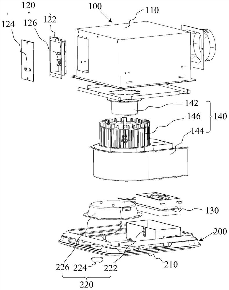
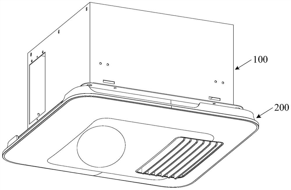
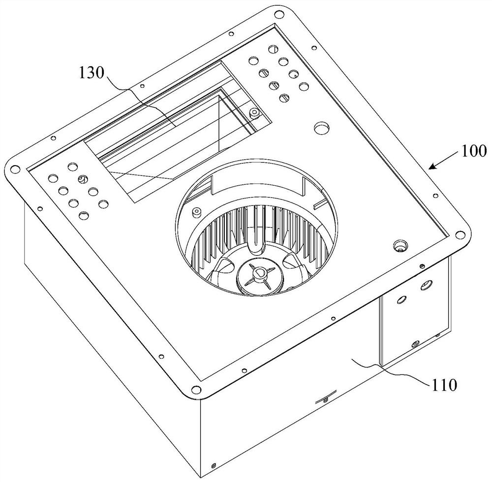
The invention relates to a multi-functional ventilator control system which is arranged in a main machine shell through a heating piece and a fan assembly. A first ventilation opening is formed in the first side face of the main machine shell. The heating piece is arranged close to the first ventilation opening. The heating piece and the fan assembly are electrically connected with a control panel assembly. The first side surface of a panel shell is mechanically connected with the first side surface of the main machine shell, the panel shell is provided with a second ventilation opening corresponding to the first ventilation opening, and the second ventilation opening is communicated with the first ventilation opening. A light-emitting assembly is electrically connected with the control panel assembly, the light-emitting assembly is arranged on the panel shell, and therefore the multiple functions of air exchange, air blowing, heating and warming and light emitting (such as light-emitting lighting and light-emitting sterilization lamps) are integrated on the ventilator, different requirements of people can be met, practicability is enhanced, and the installation space and cost are greatly reduced.

Description


Claims


Application Information

Patent Timeline
Owner 广东创富电气有限公司
Why Eureka
Try Eureka