Large forging piece forming equipment for mining machinery
A technology for forming equipment and forging parts, which is applied in the field of mining machinery forging forming devices, can solve the problems of increasing the processing difficulty of large forgings, the processing efficiency cannot meet the processing needs, and the hidden dangers of workers' safety, so as to improve processing efficiency, high degree of automation, and avoid The effect of security risks
- Summary
- Abstract
- Description
- Claims
- Application Information
AI Technical Summary
Problems solved by technology
Method used
Image

Examples
Example Embodiment
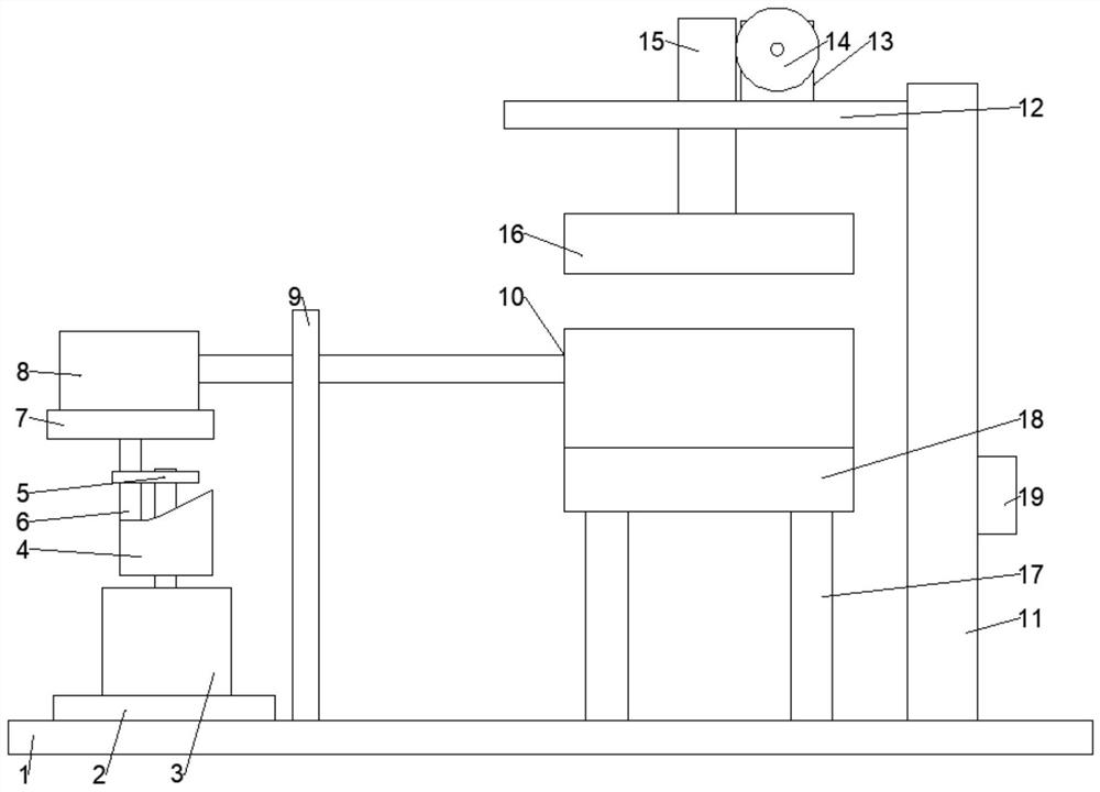
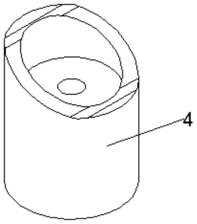
[0021] Example 1: Please refer to Figures 1 to 3 In the embodiment of the present invention, a large-scale forging part forming equipment for mining machinery includes a bottom plate 1 and a boss 2, a boss 2 is fixedly connected to the upper left side of the bottom plate 1, and a first motor 3 is fixedly connected to the upper middle of the boss 2, The middle part of the shaft of the first motor 3 is fixedly connected with the inclined wheel 4, the upper end of the shaft of the first motor 3 is rotatably connected with a connecting plate 5, and the left side of the connecting plate 5 is slidably connected with a sliding shaft 6 whose lower end slides on the upper edge of the inclined wheel 4. A mounting plate 7 is fixedly connected to the upper end of the shaft 6, an electric push rod 8 is fixedly connected above the mounting plate 7, the left end of the electric push rod 8 is slidably connected to the upper end of the column 9 that is fixedly connected to the upper left side of
Example Embodiment
[0026] Embodiment 2: This embodiment is a further improvement of the previous embodiment: a controller 19 is fixedly connected to the lower right side of the side vertical plate 11 , which is convenient for controlling the operation of each motor and the electric push rod 8 .
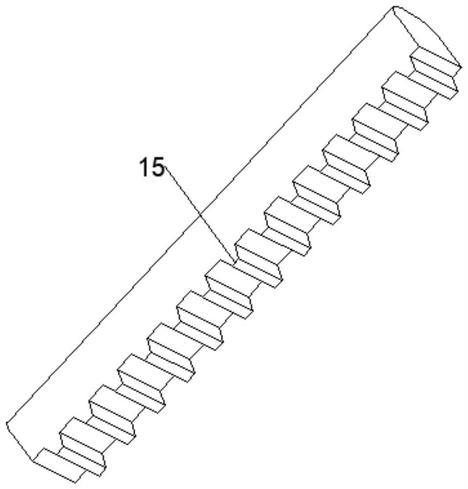
[0027] The working principle of the present invention is as follows: the first motor 3 is turned on by the controller 19, the first motor 3 drives the inclined wheel 4 to rotate, and then the sliding shaft 6 slides up and down through the sliding of the sliding shaft 6 on the upper edge of the inclined wheel 4, and then the sliding shaft 6 slides up and down. Drive the mounting plate 7 to move up and down, and then drive the electric push rod 8 to move up and down, so that the height position of the lower mold 10 can be adjusted, which is convenient for turning the workpiece. The mold 10 is taken out to avoid potential safety hazards for workers; the second motor 13 drives the gear 14 to rotate, and then dr
PUM
 Abstract
Description
Claims
Application Information
 - R&D Engineer
- R&D Manager
- IP Professional
- Industry Leading Data Capabilities
- Powerful AI technology
- Patent DNA Extraction
Browse by: Latest US Patents, China's latest patents, Technical Efficacy Thesaurus, Application Domain, Technology Topic.
© 2024 PatSnap. All rights reserved.Legal|Privacy policy|Modern Slavery Act Transparency Statement|Sitemap