Punching device applied to field of automobile manufacturing

A punching device and automobile manufacturing technology, applied in the direction of manufacturing tools, feeding devices, storage devices, etc., can solve the problems of slow manual insertion and removal, low work efficiency, and clamping of hands, so as to improve safety, Improved work efficiency and ease of movement

Pending Publication Date: 2021-05-28
ANHUI WEIWEI RUBBER PARTS GRP
View PDF6 Cites 1 Cited by
  • Summary
  • Abstract
  • Description
  • Claims
  • Application Information

AI Technical Summary

Benefits of technology

The present in this patented technology allows for efficient and safe removal or insertion of work pieces during molded parts manufacturing processes without requiring human labor input. It uses an apparatus called a slide assembly (SCA) which includes two components: one holds the work piece while it moves towards another component; and the other helps remove the work from its place inside. This system simplifies the overall structure of these systems compared to existing methods like manually placing them on top of each others. Additionally, there may be multiple rollers placed at different locations along the SCA to further enhance movement within the machine. Overall, this technical effect makes production more efficiently and safer than current solutions.

Problems solved by technology

This patented technical problem addressed in this patents relates to improving automated equipment for creation of precision metal tools used during vehicle manufacturing operations such as drilling or boring holes. Current methods require laborious manual steps like adding new materials onto the tool before it can start working properly. Additionally, there may also exist safety hazards associated with handling heavy metals while doing these tasks due to their high risk of harm caused by accidental exposure over time.

Method used


Image

  • Punching device applied to field of automobile manufacturing
  • Punching device applied to field of automobile manufacturing
  • Punching device applied to field of automobile manufacturing

Examples


Embodiment

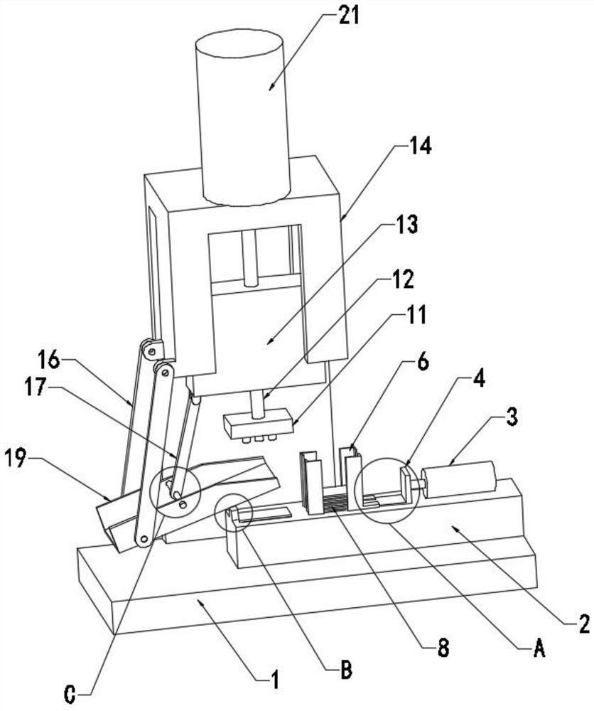
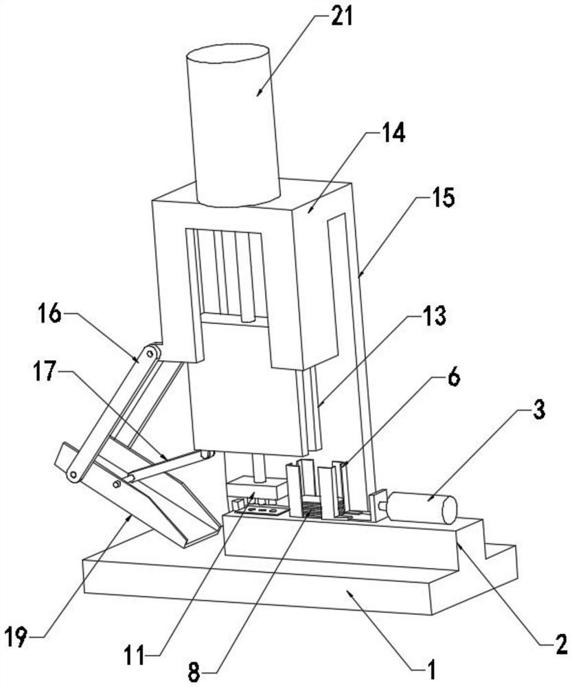
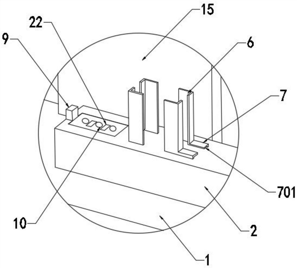
[0047] see Figure 1-10, the present invention provides a technical solution: a punching device used in the field of automobile manufacturing, including a base 1, a mounting base 2 is fixedly mounted on the top of the base 1, a lower module 10 is fixedly mounted on the mounting base 2, and a lower module 10 is fixedly mounted on the mounting base 2. The material frame 6 and the fixed block 7 are fixedly installed, and the bottom of the material frame 6 and the fixed block 7 is provided with a first groove 701, and the material frame 6 is provided with a plurality of stacked workpieces 8, and the mounting seat 2 is provided with the first groove 701. A push plate 5 that moves in a groove 701, a cylinder 3 is fixedly installed on the mounting seat 2, a mounting block 4 is fixedly mounted on the piston rod of the cylinder 3, the mounting block 4 is fixedly connected with the pushing plate 5, and the mounting block 2 is fixedly installed with The limit block 9 that restricts the move


PUM


Abstract

The invention discloses a punching device applied to the field of automobile manufacturing. The punching device comprises a base, a mounting seat is fixedly mounted at the top of the base, a die block is fixedly mounted on the mounting seat, and a material frame and a fixing block are fixedly mounted on the mounting seat. A pushing plate is driven by an air cylinder to push a workpiece to the position above the lower die block, a hydraulic cylinder is started to stretch out a piston rod, a sliding block is driven to move downwards, a second connecting rod pushes a tipping bucket to rotate to leave a mounting base, an upper die block and the lower die block are closed to punch the workpiece, the hydraulic cylinder is started to retract the piston rod, negative pressure is introduced into a negative pressure pipe to suck the workpiece, the sliding block drives the upper die block to suck the workpiece to move upwards, the sliding block moves upwards to pull the second connecting rod to drive the tipping bucket to rotate to the position below the upper die block, normal pressure is introduced into the negative pressure pipe, the workpiece falls into the inclined tipping bucket under the action of gravity and then falls into a collecting box, a punching process is completed, material putting and discharging of the workpiece are achieved through a mechanical mechanism, operation is simple, and working efficiency is improved.

Description


Claims


Application Information

Patent Timeline
Owner ANHUI WEIWEI RUBBER PARTS GRP
Why Eureka
Try Eureka