Passivation equipment and passivation method
A device and passivation box technology, applied in sustainable manufacturing/processing, electrical components, climate sustainability, etc., can solve problems such as reducing the lifting effect of half-cell modules, reducing cell efficiency, reducing module efficiency, etc., to improve optoelectronics. efficiency, ensure passivation effect, improve efficiency
- Summary
- Abstract
- Description
- Claims
- Application Information
AI Technical Summary
Benefits of technology
Problems solved by technology
Method used
Image

Examples
Embodiment 1
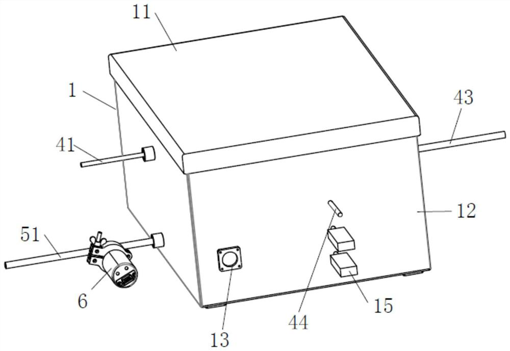
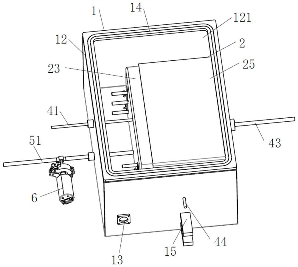
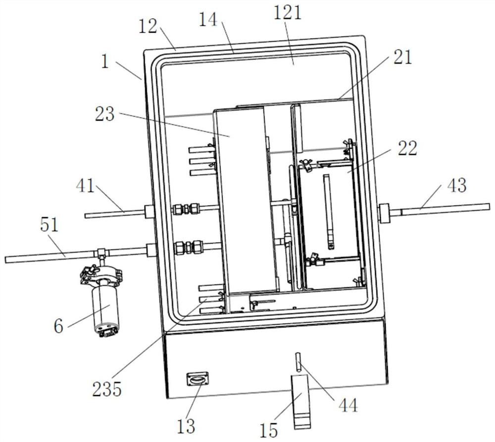
[0049] Such as Figure 1-9 As shown, a kind of passivation equipment comprises an isolation box 1, a passivation box 2 located in the isolation box 1, a carrier device 22 and a heating device 23 located inside the passivation box 2, and the carrier device 22 and the heating device 23 are arranged There is a spraying device, the carrier device 22 carries the sliced battery 3 , the heating device 23 controls the temperature in the passivation box 2 , and the spraying device sprays passivation gas on the section of the sliced battery 3 .
[0050] In this embodiment, the passivation gas is set as a mixed gas containing ozone, and the description below refers to ozone. In addition, the sliced battery 3 has at least one section.
[0051] The isolation box 1 is arranged as a square structure, and it includes an isolation body 12 and an isolation cover 11. The isolation body 12 includes an isolation cavity 121 with an opening facing upwards. The passivation box 2 is located in the
Embodiment 2
[0068] Such as Figure 10 As shown, the difference between the present embodiment and the first embodiment is that in the first embodiment, ozone is introduced by the air duct 41 and sprayed through the spray pipe 42, while in the present embodiment, the oxygen is irradiated by the ultraviolet lamp 232 Ozone is produced.
[0069] In this embodiment, the ultraviolet lamp tube 232 is fixed on the housing 231 of the heating device 23, and the ultraviolet lamp tube 232 is provided with two groups. The tube 232 is located between the adjacent heating tubes 233. In the horizontal direction, the ultraviolet lamp tube 232 is located at the rear side of the heating tube 233, that is, the heating tube 233 is located between the ultraviolet lamp tube 232 and the carrier device 22. In order to prevent the heating tube 233 from For the radiation heating of the ultraviolet lamp tube 232, a heat insulating lampshade 234 is fixed between the two sets of fixing rods 235 of one group of heating t
Embodiment 3
[0093] In this embodiment, the specific steps of the method are as follows:
[0094] (1) Sliced battery 3 is pre-installed;
[0095] The sliced battery 3 is stacked on the carrier device 2, the carrier device 2 is installed in the carrier cavity 215, and the cover plate 25 and the isolation cover plate 11 are placed in sequence
[0096] (2) vacuum leak detection;
[0097]The exhaust device is vacuumed, and the air pressure is detected by the vacuum gauge 6 to confirm the tightness of the isolation box 1; if the change in the air pressure value detected by the vacuum gauge 6 is within the allowable range, it means that the airtightness of the isolation box 1 is good.
[0098] If the air pressure value detected by the vacuum gauge 6 increases beyond a certain range, it means that the sealing performance of the isolation box 1 is poor,
[0099] The isolation box 1 needs to be sealed until the isolation box 1 is well sealed.
[0100] (3) control the temperature and pressure of
PUM
 Abstract
Description
Claims
Application Information
 - R&D Engineer
- R&D Manager
- IP Professional
- Industry Leading Data Capabilities
- Powerful AI technology
- Patent DNA Extraction
Browse by: Latest US Patents, China's latest patents, Technical Efficacy Thesaurus, Application Domain, Technology Topic.
© 2024 PatSnap. All rights reserved.Legal|Privacy policy|Modern Slavery Act Transparency Statement|Sitemap