Ceramic tile processing equipment

A technology for processing equipment and ceramic tiles, which is applied in the field of ceramic tile processing, can solve problems such as low practicability and single function of processing equipment, and achieve the effects of improving practicability, increasing functionality, and uniform temperature

Active Publication Date: 2021-06-08
新兴县致胜陶瓷有限公司
View PDF10 Cites 1 Cited by
  • Summary
  • Abstract
  • Description
  • Claims
  • Application Information

AI Technical Summary

Problems solved by technology

[0005] In order to overcome the above-mentioned defects of the prior art, an embodiment of the present invention provides a ceramic tile processing equ

Method used


Image

  • Ceramic tile processing equipment
  • Ceramic tile processing equipment
  • Ceramic tile processing equipment

Examples


Embodiment Construction

[0024] The following will clearly and completely describe the technical solutions in the embodiments of the present invention with reference to the accompanying drawings in the embodiments of the present invention. Obviously, the described embodiments are only some, not all, embodiments of the present invention. Based on the embodiments of the present invention, all other embodiments obtained by persons of ordinary skill in the art without making creative efforts belong to the protection scope of the present invention.

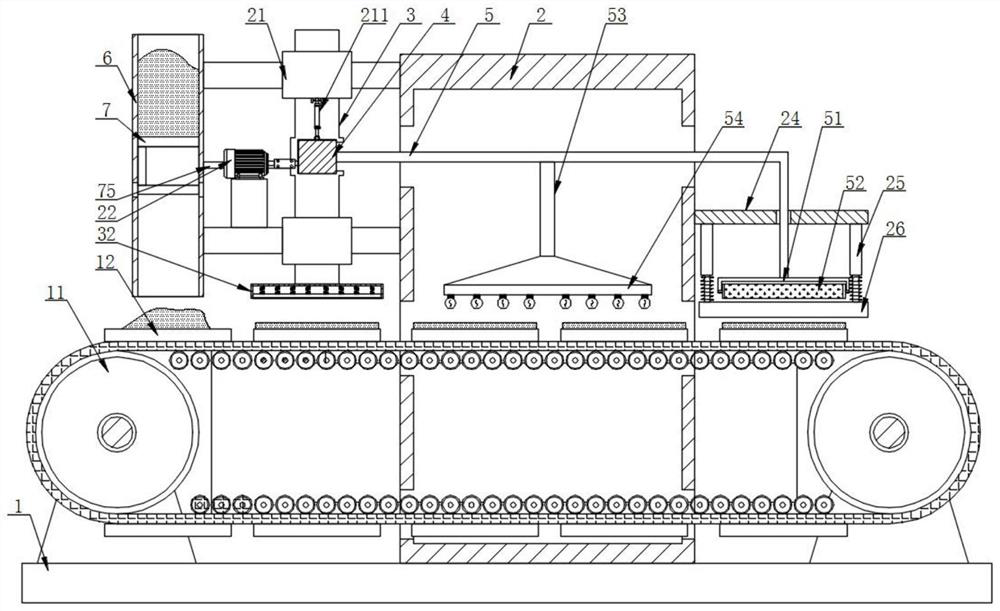
[0025] The ceramic tile processing equipment in the embodiment of the present invention may include a base plate 1, a conveying device 11 is fixedly installed on the top of the base plate 1, and evenly arranged placing plates 12 are fixedly installed on the conveyor belt surface of the conveying device 11, and the base plate The top of 1 is fixedly installed with a drying box 2 set outside the conveying device 11, and one side of the drying box 2 is fixedly instal


PUM


Abstract

The invention discloses ceramic tile processing equipment, and particularly relates to the field of ceramic tile processing. The ceramic tile processing equipment comprises a bottom plate, wherein a conveying device is fixedly mounted at the top of the bottom plate; placing plates which are uniformly arranged are fixedly mounted on the surface of a conveying belt of the conveying device; a drying box which sleeves the conveying device is fixedly mounted at the top of the bottom plate; two fixing sleeves which are distributed up and down are fixedly mounted on one side of the drying box; vertical rods are arranged in the fixing sleeves in a sliding mode; and blank pressing plates are fixedly mounted at the bottom ends of the vertical rods. According to the ceramic tile processing equipment provided by the invention, through movement of the vertical rods and transverse rods, the function of automatic intermittent blanking is achieved, the function that the blank pressing plates move up and down to automatically press and mold blanks is achieved, and a drying cylinder moves front and back and up and down in the drying box, so that hot air is evenly blown to the surfaces of green bricks, and the temperature in the drying box is ensured to be uniform; and the function of printing or glazing the surface of the dried ceramic tile blank is also realized.

Description


Claims


Application Information

Patent Timeline
Owner 新兴县致胜陶瓷有限公司
Why Eureka
Try Eureka