Wafer film coating equipment

A coating film and equipment technology, applied in the field of wafer coating equipment, can solve the problems of floating, reducing the safety of wafer coating equipment, increasing the resistance of wafers, etc., and achieve the effect of improving safety

Active Publication Date: 2021-06-18
重庆重锐纳米科技股份有限公司
View PDF9 Cites 0 Cited by
  • Summary
  • Abstract
  • Description
  • Claims
  • Application Information

AI Technical Summary

Benefits of technology

The technical effect of this patented technology prevents an excessive release or escaping of acids (acidic gases) when used for coatings on semiconductor devices such as integrated circuits. This helps reduce accidents involving operators who may accidentally get exposed while adding chemical agents onto these materials.

Problems solved by technology

This patented technical problem addressed in this patents relates to improving the performance or durability of films applied onto surfaces made of siliceous materials such as SiC substrate due to oxidative damage caused by high temperatures and moisten conditions. These layers help prevent corrosion and improve their overall effectiveness over longer periods of use without causing harmful effects like reduced device efficiency or increased risk of injury.

Method used


Image

  • Wafer film coating equipment
  • Wafer film coating equipment
  • Wafer film coating equipment

Examples


Embodiment 1

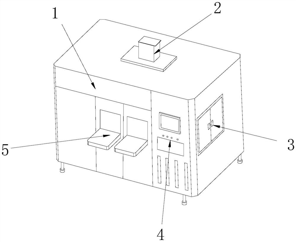
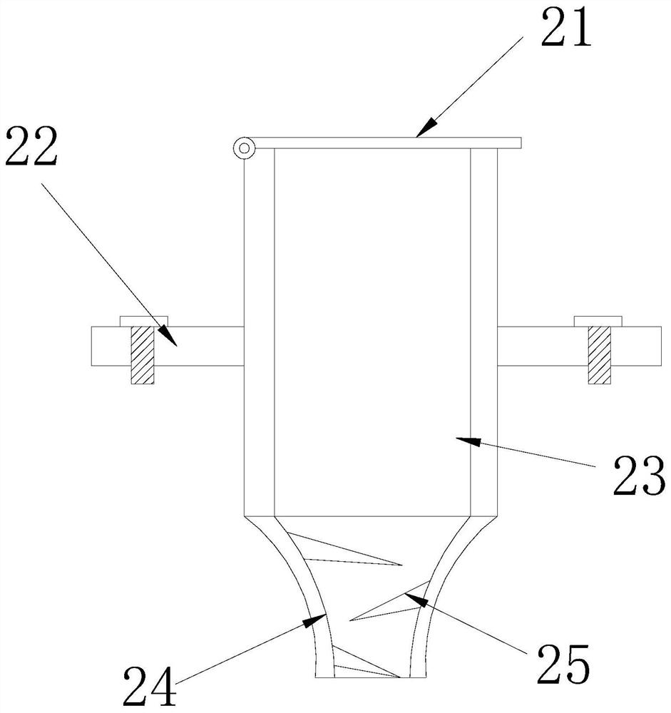
[0024] see Figure 1-Figure 5 , the specific embodiments of the present invention are as follows: a wafer coating equipment, its structure includes a body 1, a film liquid pipe 2, an inspection door 3, a control machine 4, and an input platform 5, and the film liquid pipe 2 is embedded on the top of the body 1 The two sides of the maintenance door 3 are hingedly connected to the right side of the body 1, the control machine 4 is embedded in the front of the body 1, the back of the input platform 5 is welded to the front of the body 1; the membrane liquid pipe 2 includes a sealing cover 21 , fixed plate 22, stay pipe 23, input pipe 24, blocking plate 25, the left side of the sealing cover 21 is hingedly connected with the top surface of the stay pipe 23, the top surface of the input pipe 24 is connected with the bottom surface of the stay pipe 23 and passes through Electric welding connection, one side of the blocking plate 25 is welded to the inner layer of the input pipe 24, the

Embodiment 2

[0030] see Figure 6-Figure 7 The specific embodiment of the present invention is as follows: the suction torsion wheel A15 includes a pressure handle B1, a chuck B2, a mounting ring B3, an elastic block B4, and an inner shaft B5, and the bottom end of the pressure handle B1 passes through the chuck B2 and the mounting ring The outer ring of B3 is movably engaged, the top of the elastic block B4 is embedded inside the installation ring B3, the bottom of the elastic block B4 is movably engaged with the outer ring of the inner shaft B5, and the elastic block B4 is provided with multiple, multiple elastic blocks The B4 gap is evenly embedded in the installation ring B3 in a ring shape, which is beneficial to increase the rebound speed and the pumping capacity.

[0031]Wherein, the elastic block B4 includes a soft ball B41, a twist frame B42, a twist ring B43, and a connector B44, the bottom of the soft ball B41 is movably engaged with the top of the twist frame B42, and the twist ri


PUM


Abstract

The invention discloses wafer film coating equipment. The wafer film coating equipment structurally comprises a machine body, a film liquid pipe, an access door, a control machine and an input table, wherein the film liquid pipe is embedded into the top surface of the machine body, the two sides of the access door are hinged to the right side of the machine body, the control machine is embedded into the front surface of the machine body, and the back surface of the input table is welded to the front surface of the machine body. According to the wafer film coating equipment, in a normal state, through double cooperation of a sealing cover and a staying wheel, acetone gas volatilized from a positive photoresist is prevented from drifting to the outside, when the positive photoresist needs to be added, the staying wheel in a staying pipe is pulled, gas in the staying wheel is pumped away when the staying wheel is opened, the bottom is sealed, and the top is opened; and in the feeding process, the acetone gas cannot escape, and the top can be quickly sealed after feeding is finished so that an adder cannot make in contact with the acetone gas all the time, the safety problem caused by the fact that an operator inhales a large amount of acetone gas by mistake is further avoided, and the safety of the film coating equipment during operation is greatly improved.

Description


Claims


Application Information

Patent Timeline
Owner 重庆重锐纳米科技股份有限公司
Why Eureka
Try Eureka