Microwave application reaction device and application method thereof

A technology of reaction device and microwave generating device, applied in chemical instruments and methods, chemical/physical/physicochemical process of energy application, chemical/physical/physicochemical process, etc., can solve the problem of microwave device damage, reflection back, and damage to microwave Problems such as devices occur, to achieve the effects of reducing loss, improving production efficiency and long service life

Pending Publication Date: 2021-06-29
肖琴瑛
View PDF6 Cites 0 Cited by
  • Summary
  • Abstract
  • Description
  • Claims
  • Application Information

AI Technical Summary

Benefits of technology

This patented technology allows for efficient acceleration of reactions by reducing heat generated during their production while maintaining good efficiency at high temperatures. It also simplifies the design making them suitable for use with different types of reactors that require precise temperature control or have complicated structures.

Problems solved by technology

This patented technical solution describes how certain types of electromagnetic waves (called microwaving) can cause harm when they enter into materials like plastic during processing. These radiation can lead to changes made inside these substances due to their own characteristics. To prevent this from happening, an anti-reflective coating was added between them with specific dimensions designed specifically to absorb any unwanted signals without affecting other things being processed at once.

Method used


Image

  • Microwave application reaction device and application method thereof
  • Microwave application reaction device and application method thereof
  • Microwave application reaction device and application method thereof

Examples


Embodiment Construction

[0024] In order to facilitate the understanding of those skilled in the art, the present invention will be further described below in conjunction with the embodiments and accompanying drawings, and the contents mentioned in the embodiments are not intended to limit the present invention.

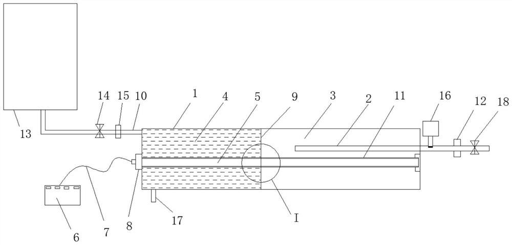
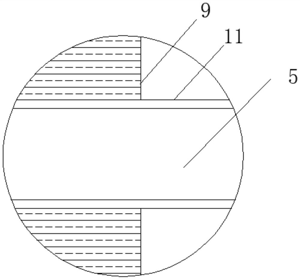
[0025] like Figure 1-3 As shown, a microwave application reaction device includes a housing 1, a microwave source device, an isolation structure, and a reaction tube 2. The housing 1 is enclosed to form an accommodating chamber, and the isolation structure is arranged in the accommodating chamber and used To divide the accommodating chamber into a non-absorbing area 43 and a wave-absorbing area 4, the non-absorbing area 43 is used for loading non-absorbing materials, and the wave-absorbing area 4 is used for loading wave-absorbing materials; the reaction The tube 2 extends into the non-absorbing area 43 from one side of the housing 1; the microwave source device includes a microwave antenna 5


PUM


Abstract

The invention relates to the field of chemical reaction devices, in particular to a microwave application reaction device and an application method thereof. The microwave application reaction device comprises a shell, a microwave source device, an isolation structure and a reaction tube, when the shell encloses to form anaccommodating chamber; the isolation structure is arranged in the accommodating chamber and is used for dividing the accommodating chamber into a non-wave-absorbing area and a wave-absorbing area; the reaction tube extends into the non-wave-absorbing area from one side of the shell; the microwave source device comprises a microwave antenna and a radio frequency microwave generating device, the microwave antenna is arranged in the accommodating cavity, the radio frequency microwave generating device is arranged outside the accommodating cavity, and the microwave antenna penetrates through the side, far away from the reaction tube, of the shell and is connected with the radio frequency microwave generating device; the microwave antenna transversely penetrates through the wave-absorbing area and the non-wave-absorbing area; and the reaction tube is made of a non-wave-absorbing material. The device is simple and compact in structure and ingenious in design, and has excellent application prospects in the field of chemical reactions.

Description


Claims


Application Information

Patent Timeline
Owner 肖琴瑛
Why Eureka
Try Eureka