Clamping groove equipment for cutting and reinforcing outer side of solid wood cutting board

A cutting board and card slot technology, which is applied to the field of card slot equipment for cutting and reinforcing the outer side of a solid wood cutting board, can solve the problems of low work efficiency, cumbersome operation process, labor consumption and the like, and achieve the effect of improving work efficiency and convenient operation.

Pending Publication Date: 2021-07-16
廖玉玲
View PDF23 Cites 0 Cited by
  • Summary
  • Abstract
  • Description
  • Claims
  • Application Information

AI Technical Summary

Problems solved by technology

[0005] In order to overcome the cumbersome operation process, low work efficiency, and relatively labor-intensive operation

Method used


Image

  • Clamping groove equipment for cutting and reinforcing outer side of solid wood cutting board
  • Clamping groove equipment for cutting and reinforcing outer side of solid wood cutting board
  • Clamping groove equipment for cutting and reinforcing outer side of solid wood cutting board

Examples


Embodiment 1

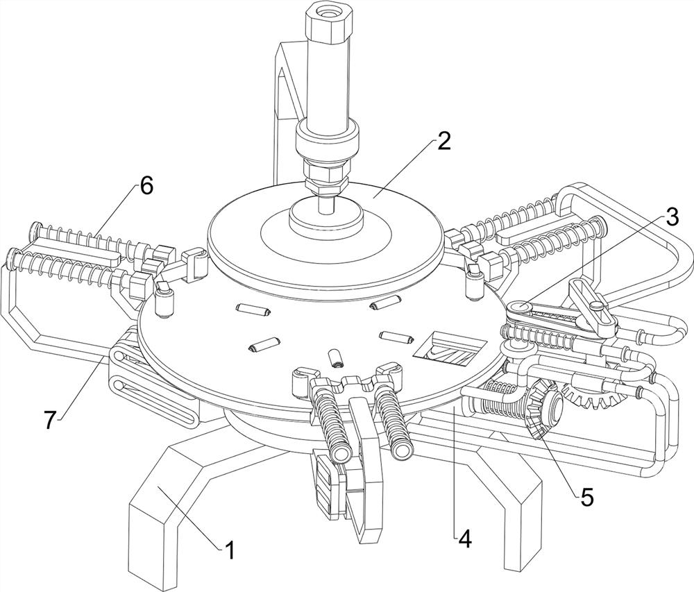
[0025] A device for cutting and reinforcing the outer side of a solid wood chopping board, such as figure 1 , figure 2 with image 3 As shown, it includes a base 1, a placing mechanism 2, a cutting mechanism 3, a rotating mechanism 4 and a driving mechanism 5. The upper middle part of the base 1 is provided with a placing mechanism 2, the right side of the placing mechanism 2 is provided with a cutting mechanism 3, and the upper right side of the base 1 A rotating mechanism 4 is provided, and a driving mechanism 5 is arranged on the rotating mechanism 4 .

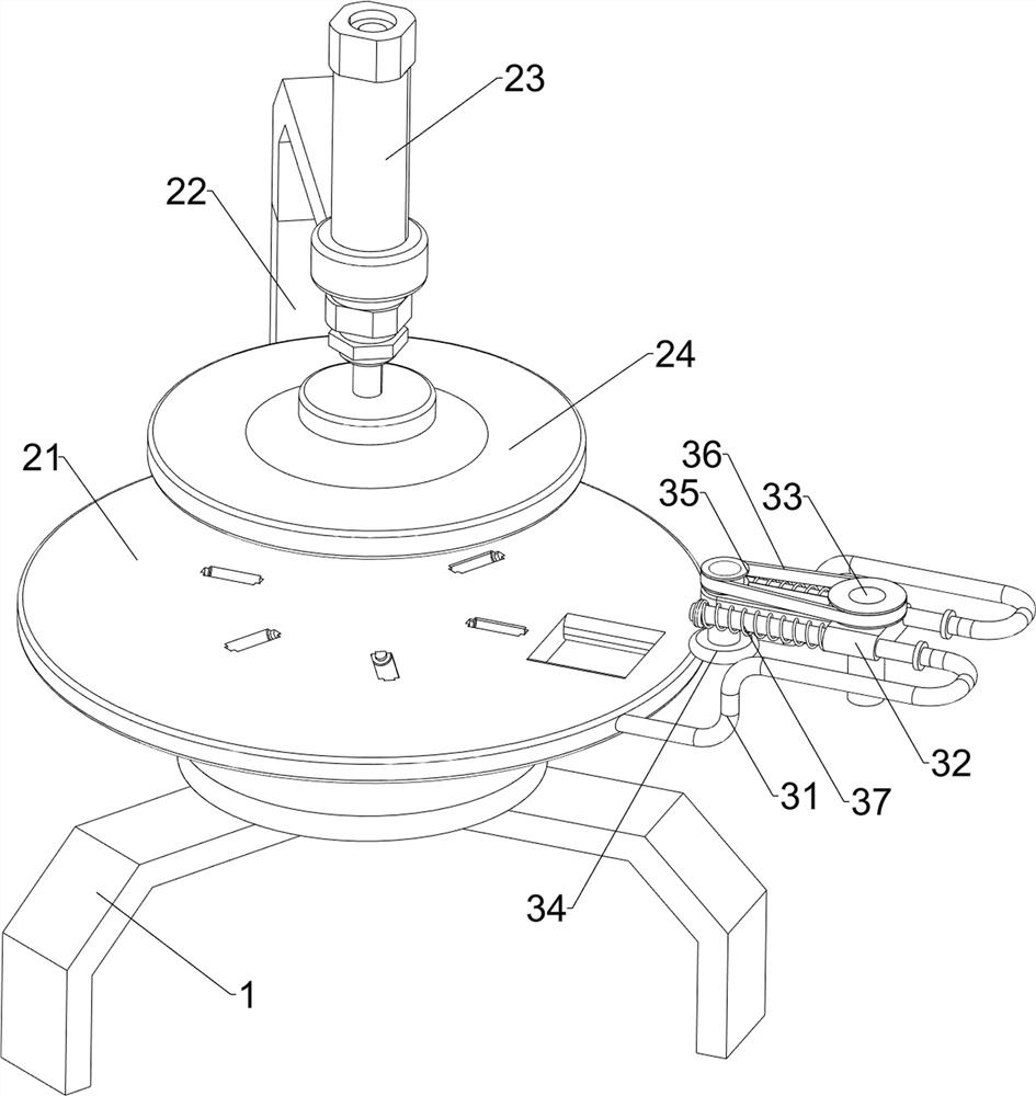
[0026] The placement mechanism 2 includes a placement tray 21, a first mounting frame 22, a cylinder 23 and a pressure plate 24. The upper middle part of the base 1 is slidingly provided with the placement tray 21, and an elastic member is arranged between the middle side of the bottom of the placement tray 21 and the base 1. The base 1. The upper rear side is provided with a first mounting frame 22, and the first mounti...

Embodiment 2

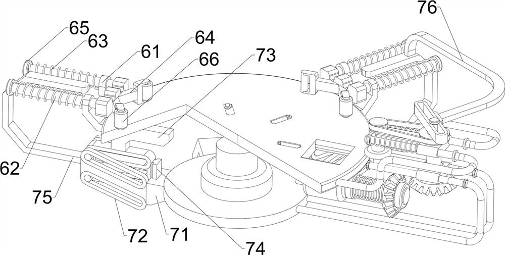
[0032] On the basis of Example 1, such as Figure 4 As shown, a centering mechanism 6 is also included, and the centering mechanism 6 includes a fourth mounting bracket 61, a sliding rod 62, a third spring 63, a connecting frame 64, a limit ring 65 and a third roller 66, placed on the outside of the disk 21 Three pairs of fourth mounting brackets 61 are evenly spaced, and sliding rods 62 are provided on the fourth mounting brackets 61. Limiting rings 65 are provided on the outside of the sliding rods 62. The third springs 63 are connected between each other, and the third springs 63 are respectively sleeved on the sliding rods 62. A connecting frame 64 is arranged between the inner sides of the sliding rods 62 on the same side, and a third roller 66 is arranged on the inner side of the connecting frame 64 in a symmetrically rotating manner.

[0033] People move the slide bar 62 inwardly through the tool, and the slide bar 62 will drive the connecting frame 64 to move inwardly,...


PUM


Abstract

The invention relates to clamping groove equipment, in particular to clamping groove equipment for cutting and reinforcing the outer side of a solid wood cutting board. The clamping groove equipment for cutting and reinforcing the outer side of the solid wood cutting board is automatic in grooving, accurate in grooving position and convenient to use. According to the technical scheme, the clamping groove equipment for cutting and reinforcing the outer side of the solid wood cutting board comprises a base, a placing mechanism, a cutting mechanism, a rotating mechanism and a driving mechanism; the placing mechanism is arranged at the upper middle part of the base; the cutting mechanism is arranged on one side of the placing mechanism; the rotating mechanism is arranged on one side of the base; and the driving mechanism is arranged on the rotating mechanism. The clamping groove equipment has the beneficial effects that under the action of the cutting mechanism, a second rotating shaft can drive a first rolling wheel and a first bevel gear to rotate, the first bevel gear can drive a cutting wheel to rotate, meanwhile, the first rolling wheel can drive a wood cutting board to rotate, and therefore the cutting wheel conducts outer side grooving work on the wood cutting board.

Description

technical field [0001] The invention relates to a slotting device, in particular to a slotting device for cutting and reinforcing the outer side of a solid wood chopping board. Background technique [0002] Cutting boards with different materials have their own characteristics, but wooden cutting boards are relatively safer because they are natural and do not add other substances, so natural wooden cutting boards are preferred. The wooden cutting board has high density, strong toughness, and is very firm to use. [0003] During the processing of wooden chopping boards, it is necessary to perform slotting work on the outside of the chopping board; for the slotting devices for processing the corners of wooden chopping boards currently on the market, there are still some problems. The cutting board is placed on the slotting equipment so that the cutting board is in contact with the slotting drill, and then the cutting board is rotated for slotting. The operation process of the...

Claims


Application Information

Patent Timeline
IPC IPC(8): B27F5/02
CPCB27F5/02
Inventor 廖玉玲
Owner 廖玉玲
Why Eureka
Try Eureka