Ejection cooling type thermoelectric power generation device

A temperature difference power generation and cooling technology, which is applied in the direction of ocean energy power generation, generator/motor, electrical components, etc., can solve the problems of power generation efficiency reduction, reliability reduction, power consumption, etc., and achieve long-term stable operation and high reliability. Effect

Active Publication Date: 2021-07-16
ZHEJIANG UNIV
View PDF3 Cites 0 Cited by
  • Summary
  • Abstract
  • Description
  • Claims
  • Application Information

AI Technical Summary

Benefits of technology

In this new design for an apparatus that uses thermal energy from fluids like water or gases, it creates cold liquor near its entrance while adding warm sea waters close enough together to improve efficiency without requiring any external electricity input. It also has several technical features such as efficient heat transfer with minimal movement components, reliable performance over time, easy maintenance, etc., which makes them ideal for use in various applications where they are needed.

Problems solved by technology

Technologies described in this patents involve exploring ways to use hydrogeology (hydrofracturing) techniques to generate oil well drilling breathing waters that hold up large amounts of pressure during sedimentary basin movements. These pressures cause sea floor currents to flow around the bottom of these areas where there may also exist other sources of ocean acidification called sulfur oxidizing bacteria. Additionally, some research suggests that naturally occurring saltwater flows along coastlines without causing harmful effects like corrosion. Therefore, the technical problem addressed by this patented relating technics involves developing an improved system for generating clean and reliable hydrogen gas fuel utilization based upon hydrocracking processes.

Method used


Image

  • Ejection cooling type thermoelectric power generation device
  • Ejection cooling type thermoelectric power generation device
  • Ejection cooling type thermoelectric power generation device

Examples


Embodiment

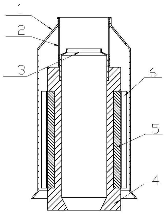
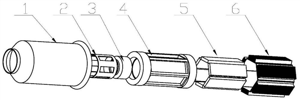
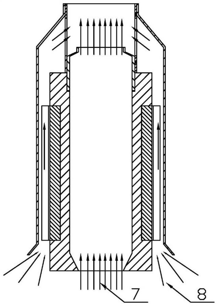
[0028] see figure 1 and figure 2 , The injection-cooled thermoelectric device of this embodiment includes a draft cover 1 , a connector 2 , a shrink tube 3 , a thermoelectric generator cavity 4 , a thermoelectric sheet 5 , and a cooling fin 6 . The shrink tube 3 is installed at the outlet of the thermoelectric generator cavity 4 through threaded connection, and the inner cavity of the shrink tube 3 is concentric with the inner cavity of the thermoelectric generator cavity 4 . One end of the connector 2 is connected to the outlet of the drainage cover 1 to ensure concentricity, and the other end is connected to the shrink tube 3 . The connecting piece 2 is a hollow cylinder supported between the thermoelectric generator cavity 4 and the diversion cover 1 , which supports and ensures that the diversion cover 1 and the thermoelectric generator cavity 4 are concentric. A liquid passage gap is formed between the drainage cover 1 and the outer wall of the thermoelectric generator ca


PUM


Abstract

The invention relates to an ejection cooling type thermoelectric power generation device, and belongs to the technical field of ocean thermoelectric energy power generation. The ejection cooling type thermoelectric power generation device comprises a thermoelectric power generation cavity, wherein the bottom part of the thermoelectric power generation cavity can be connected with a hot liquid port, the top part of the thermoelectric power generation cavity is provided with a shrinkage pipe, and high-temperature hot liquid of the hot liquid port flows out of the top shrinkage pipe through the thermoelectric power generation cavity; a thermoelectric piece arranged on the outer wall of the thermoelectric power generation cavity; and a drainage cover sleeving the thermoelectric power generation cavity, wherein a liquid passing gap is formed between the drainage cover and the outer wall of the thermoelectric power generation cavity; pressure difference is formed between the outlet of the shrinkage pipe and the drainage cover, and low-temperature seawater outside the drainage cover flows into the liquid passing gap through the bottom part of the drainage cover under pressure driving and flows out together with the high-temperature hot liquid at the top part; and jet flow erupted by the hot liquid is used for driving surrounding low-temperature seawater to flow, an original natural convection cooling mode is converted into a more efficient forced convection cooling mode, and the output power of the thermoelectric piece is increased along with the increase of the temperature of the cold end and the hot end of the thermoelectric piece. The ejection cooling type thermoelectric power generation device does not need extra electric energy consumption, does not comprise moving parts, and is high in working reliability.

Description


Claims


Application Information

Patent Timeline
Owner ZHEJIANG UNIV
Why Eureka
Try Eureka