Small wastewater treatment equipment for high-concentration wastewater

A high-concentration wastewater and wastewater treatment technology, applied in water/sludge/sewage treatment, sustainable biological treatment, water aeration, etc., can solve the problems of affecting treatment efficiency, unfavorable efficient treatment and use of wastewater, and time-consuming, etc., to achieve Ensure efficient treatment and use, improve real-time treatment efficiency, and improve the effect of real-time aeration effect

Pending Publication Date: 2021-07-20
胡跃芬
View PDF5 Cites 0 Cited by
  • Summary
  • Abstract
  • Description
  • Claims
  • Application Information

AI Technical Summary

Benefits of technology

This technology helps treat water pollution efficiently without causing environmental concerns or requiring expensive equipment that can be difficult to maintain over an extended period of use for different types of industrial processes such as gas purification systems (GSPs). It uses specialized parts called aerators that work together continuously at once, constantly moving through small holes on top of each other when there're no flowing liquid into them from one side. These tiny openings help create turbulence inside the fluid being treated, which increases its surface area exposed to oxygen compared to traditional methods where air needs to circulate around it before entering the system. By combining this process with the action of certain chemical agents like hydrogen peroxide, nitroxides, sulfur dioxins, bacteria, etc., these techniques aimed specifically towards reducing harmful substances released due to excessive amounts of organic compounds dissolved in sewage sludge. Overall, this innovative technical solution allows efficient and cost-effective wastewater treatment within reasonable timescales.

Problems solved by technology

The technical problem addressed by this patented technology relates to improving the effectiveness and speed at treating highly concentrating organics (CO) waste waters due to their unique properties such as high levels of chemical oxygen demand (C02), large amounts of ammonia released from bacterial decomposition processes with specific odors associated with harmful gases like hydrogen cyanide gas, mercaptans, tertiary butyl alcohol, chlorine dioxin, polynitrocycles, selenoxylenes, thionins, pyridines, carboximonylene, acids, aliphatones, and other volatile components found within these solvents. This can lead to environmental concerns when disposal of wastewalls poses significant challenges because conventional techniques used to dispose heavily loaded effluents cannot effectively remove certain contaminants without causing damage to the surroundings.

Method used


Image

  • Small wastewater treatment equipment for high-concentration wastewater
  • Small wastewater treatment equipment for high-concentration wastewater
  • Small wastewater treatment equipment for high-concentration wastewater

Examples


Embodiment Construction

[0029] The following will clearly and completely describe the technical solutions in the embodiments of the present invention with reference to the accompanying drawings in the embodiments of the present invention. Obviously, the described embodiments are only some, not all, embodiments of the present invention. Based on the embodiments of the present invention, all other embodiments obtained by persons of ordinary skill in the art without making creative efforts belong to the protection scope of the present invention.

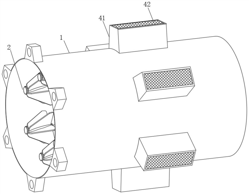
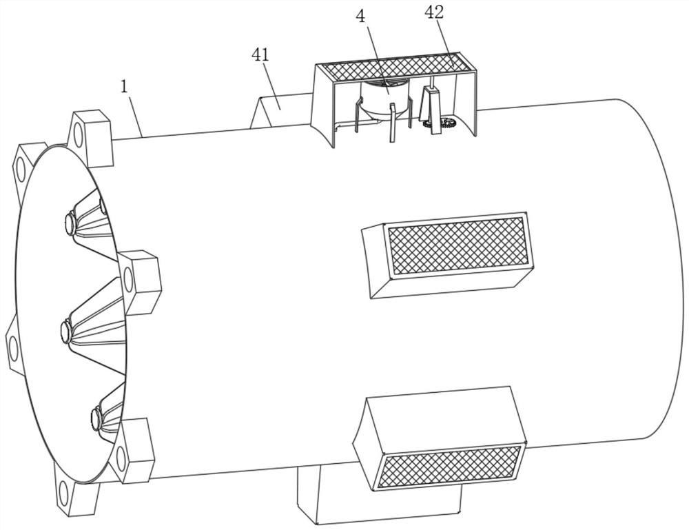
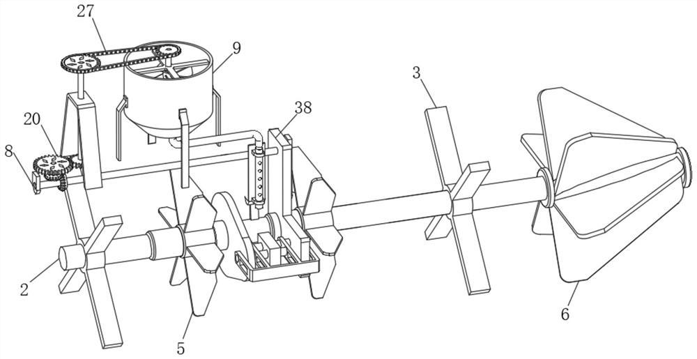
[0030] see Figure 1-10 , the present invention provides a technical solution: a small-scale wastewater treatment equipment for high-concentration wastewater, including a carrying pipe 1, the carrying pipe 1 is a conventional circular pipe structure in the prior art, but not limited, during actual use , to match the structural characteristics of the waste water delivery pipeline, so that it is installed at the nozzle position of the waste water delivery pipeline,


PUM


Abstract

The small wastewater treatment equipment comprises a bearing pipe, a functional main shaft is arranged in the bearing pipe, functional supports are rotationally installed at the two ends of the functional main shaft through bearings, and the functional main shaft is fixed in the bearing pipe through the functional supports. Compared with the prior art, the small wastewater treatment equipment for high-concentration wastewater has the advantages that stable and effective synchronous driving is provided, and meanwhile, continuous and effective functional pre-aeration treatment is carried out in the continuous wastewater conveying process; meanwhile, synchronous and effective mixing and turbulent flow are performed on the wastewater in the action process of the functional turbulent flow component; therefore, the wastewater conveyed in real time is effectively disturbed, and the real-time aeration effect is effectively improved, so that the high-concentration wastewater conveyed in real time is subjected to economical, effective and environment-friendly pretreatment, the real-time treatment efficiency of the high-concentration wastewater is effectively improved, and efficient treatment and use of the high-concentration wastewater are guaranteed.

Description


Claims


Application Information

Patent Timeline
Owner 胡跃芬
Why Eureka
Try Eureka