Electronic device

A technology for electronic equipment and equipment, applied in the field of communication, can solve problems such as poor heat dissipation effect, and achieve the effect of improving heat dissipation performance, improving user experience, and improving heat dissipation efficiency

Active Publication Date: 2021-07-20
VIVO MOBILE COMM CO LTD
View PDF8 Cites 0 Cited by
  • Summary
  • Abstract
  • Description
  • Claims
  • Application Information

AI Technical Summary

Benefits of technology

This patented technology allows for efficient transferring thermal energy between two areas by allowing fluid (liquid) containing both electrical conductive material and liquid crystal molecules to move through an elongate tube filled with air or another gas under pressure. By connecting these components together via flexibility screens made up of metal foils covered on plastic films, they can bend without losing their effectiveness due to gravity forces during use. Overall, it enhances how well the devices work properly even after being bent repeatedly over many times.

Problems solved by technology

This patented technical solution described by this patents allows for efficient cooling without affecting any other areas where there may be too much or insufficient air flow during operation due to differences in temperatures at different parts of an electronics device.

Method used


Image

  • Electronic device
  • Electronic device
  • Electronic device

Examples


Embodiment Construction

[0023] Embodiments of the present invention will be described in detail below, examples of which are shown in the drawings, wherein the same or similar reference numerals denote the same or similar elements or elements having the same or similar functions throughout. The embodiments described below by referring to the figures are exemplary only for explaining the present invention and should not be construed as limiting the present invention. Based on the embodiments in this application, all other embodiments obtained by persons of ordinary skill in the art without creative efforts fall within the protection scope of this application.

[0024] The features of the terms "first" and "second" in the description and claims of the present application may explicitly or implicitly include one or more of these features. In the description of the present invention, unless otherwise specified, "plurality" means two or more. In addition, "and / or" in the specification and claims means at


PUM


Abstract

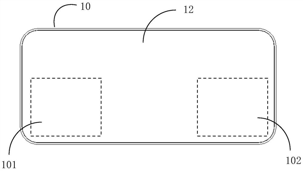
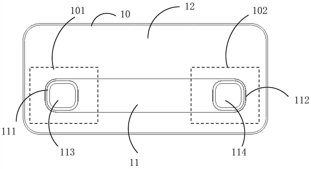
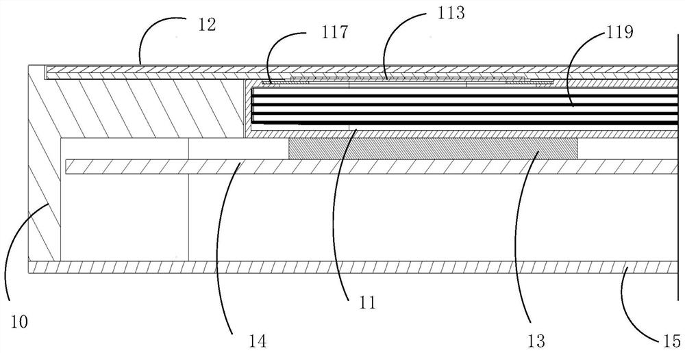
The embodiment of the invention provides electronic equipment. The electronic equipment specifically comprises an equipment body, a flexible display screen and a heat pipe, the flexible display screen is arranged on the equipment body, and the flexible display screen is provided with a first flexible pressing area and a second flexible pressing area; the heat pipe is arranged in the equipment body, a cooling medium is arranged in the heat pipe, and two ends of the heat pipe are respectively an evaporation end and a condensation end; the evaporation end is provided with a first pressing piece, the first pressing piece is connected with the flexible display screen of the first flexible pressing area, the condensation end is provided with a second pressing piece, and the second pressing piece is connected with the flexible display screen of the second flexible pressing area; when the first flexible pressing area is pressed, the cooling medium flows from the evaporation end to the condensation end, and when the second flexible pressing area is pressed, the cooling medium flows from the condensation end to the evaporation end.

Description


Claims


Application Information

Patent Timeline
Owner VIVO MOBILE COMM CO LTD
Why Eureka
Try Eureka