Filling and capping machine

A capping machine and filling technology, which is used in bottle filling machines, packaging, closures, etc., can solve problems such as low filling efficiency, and achieve the effect of improving filling efficiency and fast loading and unloading.

Pending Publication Date: 2021-09-03
中山市爱儿乐食品有限公司
View PDF0 Cites 2 Cited by
  • Summary
  • Abstract
  • Description
  • Claims
  • Application Information

AI Technical Summary

Benefits of technology

This patented technology allows for efficient and continuous filling of containers while maintaining their alignment during handling or transferring them between processing stations. By coordinating movements on both the rotor and the container, the filled product may move smoothly through different stages of production processes without any impacts caused by these movement steps.

Problems solved by technology

This patented technology describes an existing method used during manufacturing processes where fillings or caps must travel along different paths before being placed onto each container. Current methods require that all parts move together with one another when starting from start-up until they reach their final destination.

Method used


Image

  • Filling and capping machine
  • Filling and capping machine
  • Filling and capping machine

Examples


Embodiment Construction

[0034] Embodiments of the present invention are described in detail below, examples of which are shown in the drawings, wherein the same or similar reference numerals designate the same or similar elements or elements having the same or similar functions throughout. The embodiments described below by referring to the figures are exemplary only for explaining the present invention and should not be construed as limiting the present invention.

[0035] In the description of the present invention, it should be understood that the orientation descriptions, such as up, down, front, back, left, right, etc. indicated orientations or positional relationships are based on the orientations or positional relationships shown in the drawings, and are only In order to facilitate the description of the present invention and simplify the description, it does not indicate or imply that the device or element referred to must have a specific orientation, be constructed and operated in a specific ori


PUM


Abstract

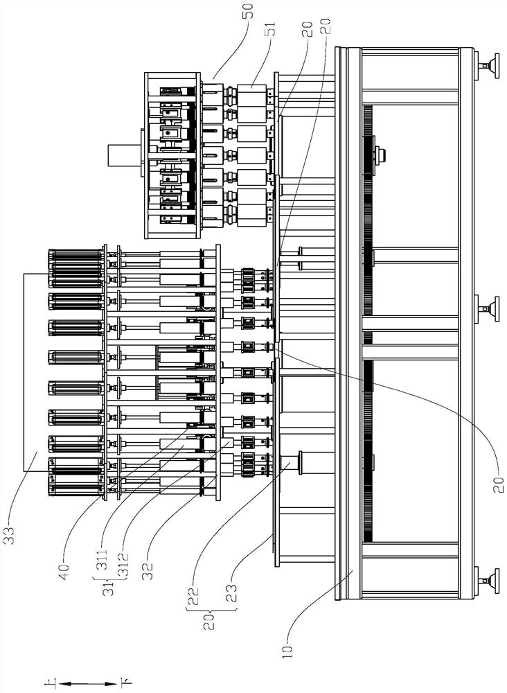
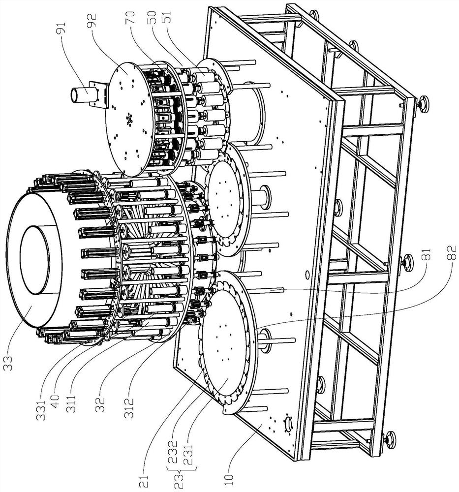
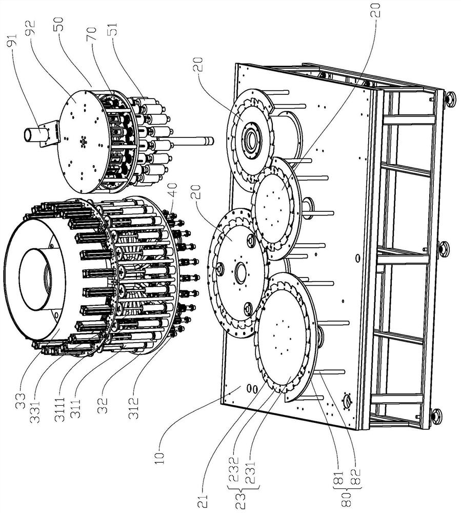
The invention discloses a filling and capping machine. The filling and capping machine comprises a rack, a conveying mechanism, a filling mechanism and a lifting mechanism, the conveying mechanism is rotatably arranged on the rack, the conveying mechanism comprises at least one rotating disc, a plurality of clamping positions used for hanging workpieces are arranged on the rotating disc in the circumferential direction, the filling mechanism is configured to be linked with one rotating disc, the filling mechanism comprises a plurality of filling units, the filling units are in one-to-one correspondence with the clamping positions of the rotating discs matched with the filling units, filling parts capable of filling the workpieces are arranged on the filling units, the filling parts can be inserted into the workpieces and can move up and down, the lifting mechanism comprises a plurality of lifting units, the lifting units correspond to the filling units in a one-to-one mode, and the lifting units are used for driving the filling parts of the filling units to move away from the workpieces after the workpieces are filled. Feeding, filling and discharging of the adjacent workpieces are not mutually influenced, the workpieces can be conveyed continuously, filling work can be carried out without stopping, rapid feeding and discharging are achieved, the filling efficiency can be greatly improved, and large-batch production can be achieved.

Description


Claims


Application Information

Patent Timeline
Owner 中山市爱儿乐食品有限公司
Why Eureka
Try Eureka