Tire vulcanization production line

A tire vulcanization and production line technology, applied in tires, household appliances, other household appliances, etc., can solve the problem of low material filling efficiency and achieve the effect of improving filling efficiency

Pending Publication Date: 2022-05-13
青岛科捷机器人有限公司
View PDF0 Cites 0 Cited by
  • Summary
  • Abstract
  • Description
  • Claims
  • Application Information

AI Technical Summary

Problems solved by technology

[0004] However, when using a vertical vulcanizing machine for production at present, due to the need to continuously install tire molds and more operations, it is generally carried out by manual filling of materials, resulting in low efficiency of material filling

Method used


Image

  • Tire vulcanization production line
  • Tire vulcanization production line
  • Tire vulcanization production line

Examples


Example Embodiment

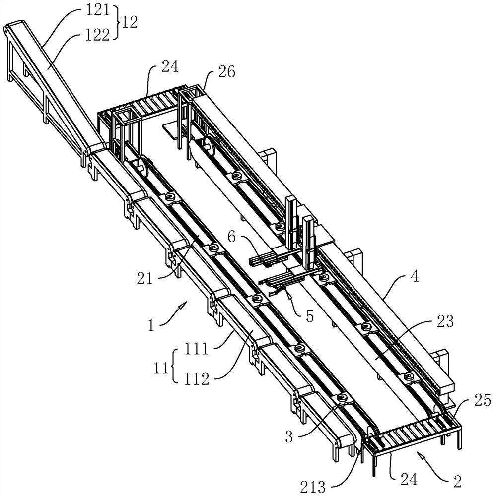
[0067] Attached to the following Figure 1-7 This application will be described in further detail.

[0068] The embodiment of the present application discloses a tire vulcanization production line, which is mainly used in the field of tire vulcanization production.

[0069] refer to figure 1 , a tire vulcanization production line, including a discharge conveying system 1, a rotary conveying system 2 and a mobile clamping unit.

[0070] When setting up the production line, firstly, multiple vertical vulcanizers are arranged along the same straight line, and the filler sides of the multiple vertical vulcanizers are all facing the same side. Then, the discharge conveying system 1 is arranged horizontally on the discharge side of the multiple vertical vulcanizers, and the conveying direction of the discharge conveying system 1 is the same as the placement direction of the multiple vertical vulcanizers. The machine-vulcanized tire can be directly placed in the discharge conveying s


PUM


Abstract

The invention relates to the field of vulcanization production lines, in particular to a tire vulcanization production line which comprises a rotary conveying system which is horizontally and annularly arranged on the filler side of a vertical vulcanizing machine, and a plurality of tool plates are arranged on the rotary conveying system and used for placing forming dies; the tool plates can be driven by the rotary conveying system to move annularly. The filling system is movably arranged above the rotary conveying system along the filling direction perpendicular to the vertical vulcanizing machine and is used for conveying the moulding bed on the tooling plate to the vertical vulcanizing machine; and the material taking system is movably arranged above the rotary conveying system in the direction perpendicular to the filling direction of the vertical vulcanizing machine, and is used for taking out the materials in the vulcanizing machine and placing the materials in the discharging conveying system. The device has the effect of improving the material filling efficiency.

Description


Claims


Application Information

Patent Timeline
Owner 青岛科捷机器人有限公司
Why Eureka
Try Eureka