Industrial robot welding clamp
A technology of industrial robots and welding fixtures, applied in manufacturing tools, welding equipment, auxiliary welding equipment, etc., can solve the problems of poor metal pipe holding effect and inconvenient welding of metal pipes, avoiding manual centering and facilitating welding. , the effect of reducing friction
- Summary
- Abstract
- Description
- Claims
- Application Information
AI Technical Summary
Problems solved by technology
Method used
Image

Examples
Embodiment 1
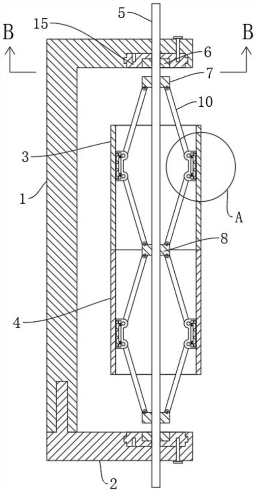
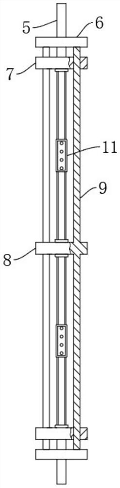
[0025] refer to Figure 1-4 , an industrial robot welding jig, including a support base 1, also includes: a support plate 2, slidingly connected to one side of the support base 1; a rotating threaded rod 5, connected between the support base 1 and the support plate 2; symmetrical The fixed block 6 is rotatably connected to both sides of the rotating threaded rod 5; wherein, the symmetrical fixed block 6 is symmetrically fixedly connected with a guide rod 9; 9 fixed connections; the symmetrical moving blocks 7 are all threaded on the rotating threaded rod 5, and are respectively located on both sides of the fixed block 8; the paired clamping blocks 11 are respectively connected on both sides of the fixed block 8, And it is located between the fixed block 8 and the moving block 7; wherein, the clamping block 11 is connected with a push rod 10 for symmetrical rotation, and the end of the symmetrical push rod 10 away from the clamping block 11 rotates with the fixed block 8 and th...
Embodiment 2
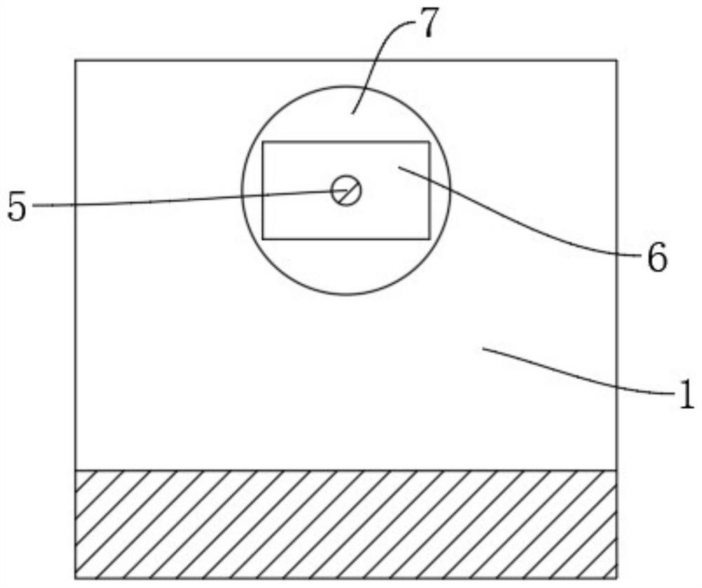
[0029] refer to Figure 1-3 , a welding fixture for an industrial robot, which is basically the same as Embodiment 1, and furthermore: includes a first pipe fitting 3, a second pipe fitting 4, and the inner walls of the supporting base 1 and the supporting plate 2 are rotatably connected with a rotating block 15, rotating The block 15 is provided with a rectangular groove matching the fixed block 6, and the rotating threaded rod 5 is connected to the supporting base 1 and the supporting plate 2 in rotation.
[0030] The rotating block 15 is provided with multiple sets of fixing holes, and the supporting base 1 and the supporting plate 2 are slidably connected with fixing pins matching the fixing holes.
[0031] Because the supporting base 1 is rotatably connected with the rotating block 15, and the rotating block 15 is provided with a rectangular groove matched with the fixed block 6, when the rotating threaded rod 5 is clamped to the pipe, the fixed pin and the rotating block...
Embodiment 3
[0033] refer to figure 1 , figure 2 , Figure 4 , a welding fixture for an industrial robot, which is basically the same as in Embodiment 1, furthermore: a sliding plate 12 is slidably connected to the clamping block 11, and a plurality of groups of rotating balls 14 are rotatably connected to the sliding plate 12, and the rotating balls 14 and The inner walls of the fittings are in close contact.
[0034] Multiple sets of thrust springs 13 are connected inside the clamping block 11 , and both ends of the thrust springs 13 are fixedly connected to the clamping block 11 and the sliding plate 12 respectively.
[0035]When the clamping block 11 is close to the inner wall of the pipe fitting, the rotating ball 14 on the sliding plate 12 in the clamping block 11 first contacts the inner wall of the pipe fitting, and when the rotating ball 14 contacts the inner wall of the pipe fitting, stop rotating the threaded rod 5. By pushing the pipe fittings, the two sections of pipe fitt...
PUM
 Abstract
Description
Claims
Application Information
 - R&D Engineer
- R&D Manager
- IP Professional
- Industry Leading Data Capabilities
- Powerful AI technology
- Patent DNA Extraction
Browse by: Latest US Patents, China's latest patents, Technical Efficacy Thesaurus, Application Domain, Technology Topic.
© 2024 PatSnap. All rights reserved.Legal|Privacy policy|Modern Slavery Act Transparency Statement|Sitemap