Cooling water circulation system of calcining coke cooler

A technology of circulation system and cold coke machine, applied in the direction of coke cooling, water shower cooler, coke oven, etc., can solve the problems of large water consumption, reduce the quality and output of needle coke, heat waste, etc. effect, reduce the content of water mist, and achieve a high degree of integration

Pending Publication Date: 2021-11-23
辽宁宝来生物能源有限公司
View PDF0 Cites 0 Cited by
  • Summary
  • Abstract
  • Description
  • Claims
  • Application Information

AI Technical Summary

Problems solved by technology

[0002] Needle coke is a high-quality variety that is vigorously developed among carbon materials. Its appearance is a silver-gray porous solid with metallic luster. The width ratio is like a fibrous or needle-like texture, and it feels smooth to the touch. It is the raw material for the production of high-end carbon products such as ultra-high-power electrodes, special carbon materials, carbon fibers and their composite materials. Due to the needle coke after calcination The temperature is very high. In the prior art, it is generally cooled by a rotary cooler. The water spraying device directly sprays water on the high-temperature needle coke in the cooler for cooling and sprays water on the cylinder of the cooler for cooling. Because the cooling water Direct contact with high-temperature needle coke will cause a reaction, which reduces the quality and output of needle coke. Therefore, some manufacturers refer to the principle of the drum slag cooler and use jacket water circulation to cool the hot coke through a membrane cold coke machine. , can effectively avoid the direct contact between the cooling water and the high-temperature needle coke, and the heat is absorbed by the water in the barrel wall of the film-type cold coke machine, thereby cooling the high-temperature needle coke. However, the high-temperature water after heat exchange needs to be cooled rapidly , to be able to achieve the purpose of recycling. In the prior art, the cooling cycle of high-temperature circulating water is mostly carried out through the cooling tower. The existing cooling tower structure is relatively simple. During the cooling operation, the water consumption is large and the heat exchange and cooling efficiency is not good. High, the waste of heat is relatively serious, and it is easy to generate a large amount of fog, which affects the quality of the surrounding environment of the factory. In view of this, in-depth research on the above problems led to this case.

Method used


Image

  • Cooling water circulation system of calcining coke cooler
  • Cooling water circulation system of calcining coke cooler
  • Cooling water circulation system of calcining coke cooler

Examples


Example Embodiment

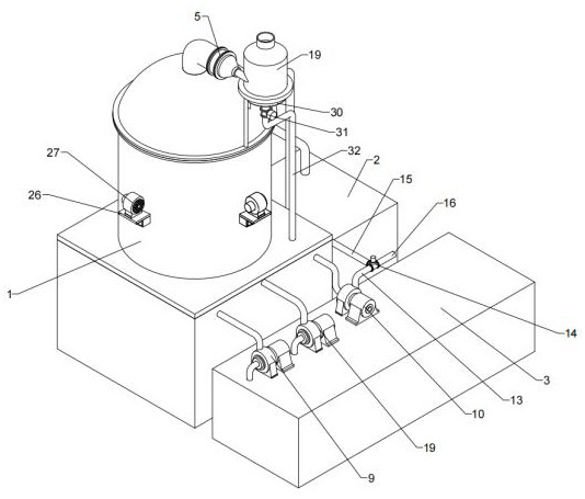
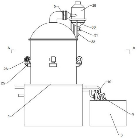
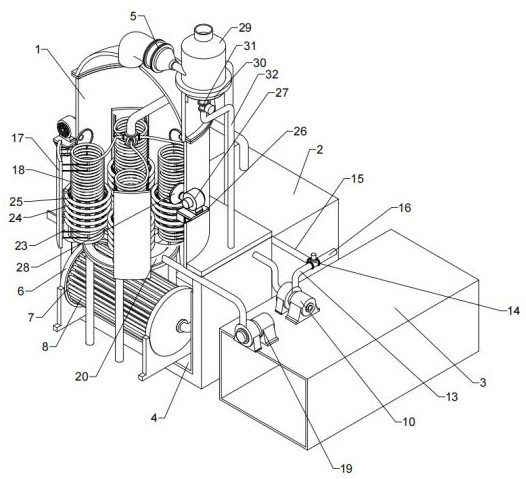
[0027] EXAMPLE: Attached Figure 1-8It can be seen that the present scheme includes a cold water column 1 and a circulating water tank 2, which is disposed on the cold water tank 1 on the cold water tower 1 and is in communication with the backwater of the cold water column 1, and an immersion heat exchange mechanism is provided at the lower portion of the cold water tower 1, immersion The refrigerating end of the heat exchange mechanism is in communication with the circulating water returning pipe, and the upper portion of the immersion heat exchange mechanism is connected to the spray cooling mechanism, and the upper portion of the spray cooling mechanism is connected to the air-cooling and cooling mechanism, the upper end vent position of the cold water column 1 The water mist separation mechanism is provided, and the high temperature circulating water after the heat transfer after the film-type cold circuit is introduced into the immersion heat exchange mechanism, and the high tem


PUM


Abstract

The invention discloses a cooling water circulation system of a calcining coke cooler. The cooling water circulation system comprises a cooling water tower and a circulation water tank, wherein the circulation water tank is arranged on one side of the cooling water tower and communicates with a water return port of the cooling water tower, an immersion type heat exchange mechanism is arranged on the lower portion of the cooling water tower, the water inlet end of the immersion type heat exchange mechanism communicates with a circulation water return pipeline. and the upper portion of the immersion type heat exchange mechanism communicates with a spraying and cooling mechanism. According to the cooling water circulation system, by means of the cooperation of the three stages of cooling mechanisms, the temperature of cooled circulating water can meet the recycling requirement, the cooled circulating water flows back into a circulating water tank to be temporarily stored, meanwhile, a water mist separation mechanism is arranged on the upper portion of the cooling water tower, gas-mist separation can be carried out on upward water vapor generated in the whole cooling process, so that the content of water mist in exhausted gas is effectively reduced, the influence on the surrounding environment is effectively reduced, and a water cooling tower adopts a closed structural design and is compact in structure, high in integration degree and higher in heat utilization rate.

Description


Claims


Application Information

Patent Timeline
Owner 辽宁宝来生物能源有限公司
Why Eureka
Try Eureka